5238-E P-298
SECTION 12 USER TASK
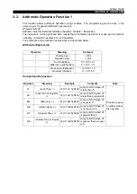
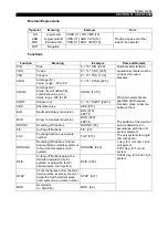
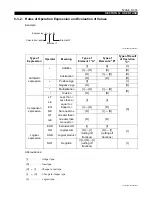
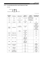
4-2-2. Output Variables
LE33013R0301400410001
The output variable numbers are tabled below.
Details of specifications must be discussed.
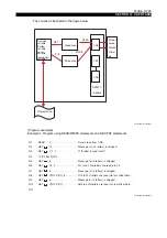
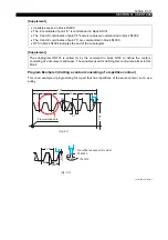
4-3.
Arithmetic Operation Function 2
The arithmetic operation function of User Task 2 provides features not supported by User Task 1;
boolean expressions and functions can be used.
For details on the arithmetic operation functions of User Task 1, refer to "Arithmetic Operation
Function 1".
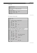
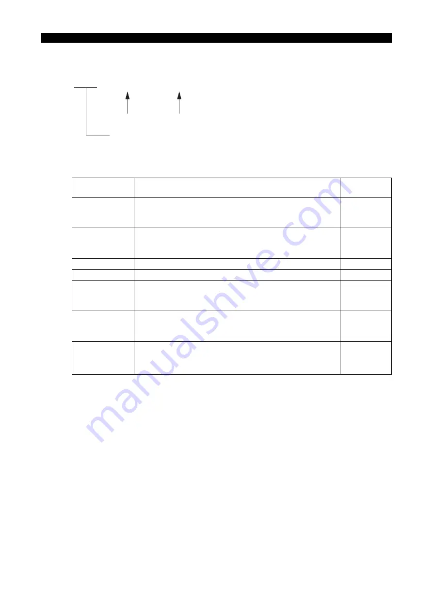
Output Variable
No.
Contents of Data
Output
Equipment
1 ~ 8
Bit data: 0 (OFF), 1 (ON)
Panel output
9
1 byte data in which data of variables #1 through #8 correspond
to bit 0 through bit 7.
11 ~ 18
Bit data: 0 (OFF), 1 (ON)
EC output
19
1 byte data in which data of variables #11 through #18
correspond to bit 0 through bit 7.
21 ~ 22
Bit data: 0 (OFF), 1 (ON)
Panel output
23 ~ 24
Bit data: 0 (OFF), 1 (ON)
EC output
31 ~ 38
Bit data: 0 (OFF), 1 (ON)
Panel output
39
1 byte data in which data of variables #31 through #38
correspond to bit 0 through bit 7.
41 ~ 48
Bit data: 0 (OFF), 1 (ON)
49
1 byte data in which data of variables #41 through #48
correspond to bit 0 through bit 7.
991
Alarm C User reserve code
Alarm output
992
Alarm B User reserve code
993
Alarm A User reserve code
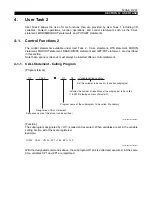
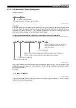
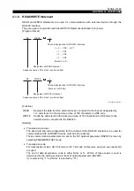
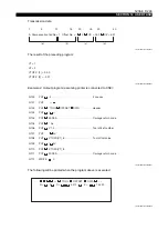
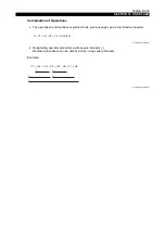
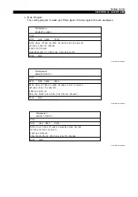
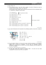
VDOUT
[Output variable no.]
Right bracket
Data OUTput
Left bracket
⋅⋅⋅⋅⋅⋅⋅⋅⋅⋅⋅⋅⋅⋅⋅⋅⋅⋅⋅⋅⋅⋅⋅⋅
Represents an output variable


