


5238-E P-128
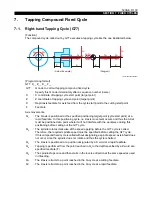
SECTION 7 FIXED CYCLES
6-3.
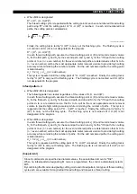
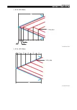
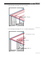
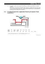
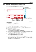
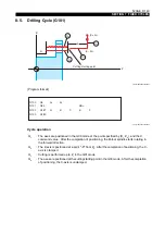
Transverse Grooving/Drilling Fixed Cycle (G74)
In the G74 mode, a grooving cycle is performed as shown below.
LE33013R0300900210001
[Programming format]
G74 X__ Z__ I__ K__ D__ L__ F__ E__ T__
X
: X coordinate of target point
Z
: Z coordinate of target point
I
: Shift amount in X-axis direction
(as a diameter; if no I word is specified, the control assumes I = 0)
K
: Shift amount in Z-axis direction (if no K word is specified, the control assumes K = 0)
D
: Depth of cut (infeed amount)
L
: Total infeed amount for tool withdrawal motion
(The sequence is not performed when no L word is specified.)
D
A
: Retraction amount "a" is specified. When no DA word is specified, the amount set at Pecking
amount in grooving and drill cycle of optional parameter (OTHER FUNCTION 1) is used as
the retraction amount. This applies both in the G94 and G95 modes.
E
: Duration of dwell when target point on Z-axis is reached
(Command unit is the same as an F word in G04 mode.)
If no E word is specified, this sequence is not performed.
T
: Tool offset number determining the tool offset amount when target point on X-axis is reached.
(If no T word is specified, the tool offset number selected on positioning to the starting point
of the grooving cycle is selected. The T command after this block is the one designated when
positioning to the starting point is performed.)
T when positioning to the
coordinates of the starting point
T when positioning to the
coordinates of the target point
End point
Starting point
Z
X
E
K
I/2
D
D
D
α
L
L


