


5238-E P-30
SECTION 3 MATH FUNCTIONS
4.
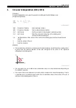
Automatic Chamfering
When cutting a workpiece, it is often necessary to chamfer a sharp edge (either straight-line
chamfering (C-chamfering) or rounding). Although such chamfering can be accomplished using
conventional interpolation commands (G01, G02, G03), the automatic chamfering function permits
chamfering to be done with a simple program.
For chamfering at any required angle, the automatic any-angle chamfering function should be used.
To use the automatic chamfering function, set "1" for optional parameter (OTHER FUNCTION 1)
Auto. any-angle chamfering. If the automatic any-angle chamfering function is required, set "any-
angle chamfering" for this parameter.
4-1.
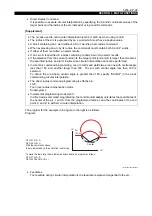
C-chamfering (G75)
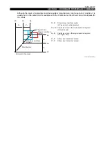
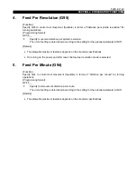
LE33013R0300500050001
To cut the contour shown above along the points A, B, D and E, program as follows:
G75 G01 X120 L-5 FDD CR
after positioning the cutting tool at point A.
With the commands above, the cutting tool moves from point A to B and then to D, thus
automatically chamfering the corner at 45 with a size of 5 mm.
When the coordinates of point E are commanded, the cutting tool moves from Point D to Point E.
[Details]
•
G75 is effective only in the G01 mode. If G75 is specified in another mode, it causes an alarm.
•
G75 is non-modal and active only in the commanded block.
•
If the axis movement dimension specified in the block calling for automatic chamfering (A - C in
the figure above) is smaller than the absolute value of the L word (B - C in the figure above), an
alarm results.
•
If the axis movement dimensions specified in the block calling for automatic chamfering are
zero both for X and Z, or if neither the X nor the Z value is zero in such a block, an alarm occurs.
The block calling for the automatic chamfering mode can contain only one dimension word,
either X or Z.
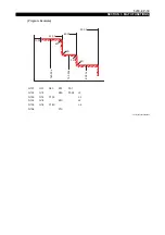
G75 : Specifies C-chamfering
X120 : X coordinate of Point C
L-5
: Size of chamfered face
The sign is determined by the direction of axis movement;
"+" when the Z-axis (X-axis) moves in the positive direction after X-axis (Z-axis) motion.
"-" when the Z-axis (X-axis) moves in the negative direction after X-axis (Z-axis) motion.
+X
+Z
(X120.00, Z50.00)
(X120.00, Z115.00)
C (X120.00, Z120.00)
B (X110.00, Z120.00)
A (X50.00, Z120.00)
E
D
5C


