-
59
-
After
setting
all
the
axes
that
will
perform
an
interpolation
for
a
postponed
start,
write
the
CSTA
output
command
06h
(simultaneous
start)
to
any
of
these
axes
and
all
of
the
axes
that
will
perform
the
interpolation
will
start
at
the
same
time.
Other
axes
that
are
not
interpolating
can
be
operated
independently.
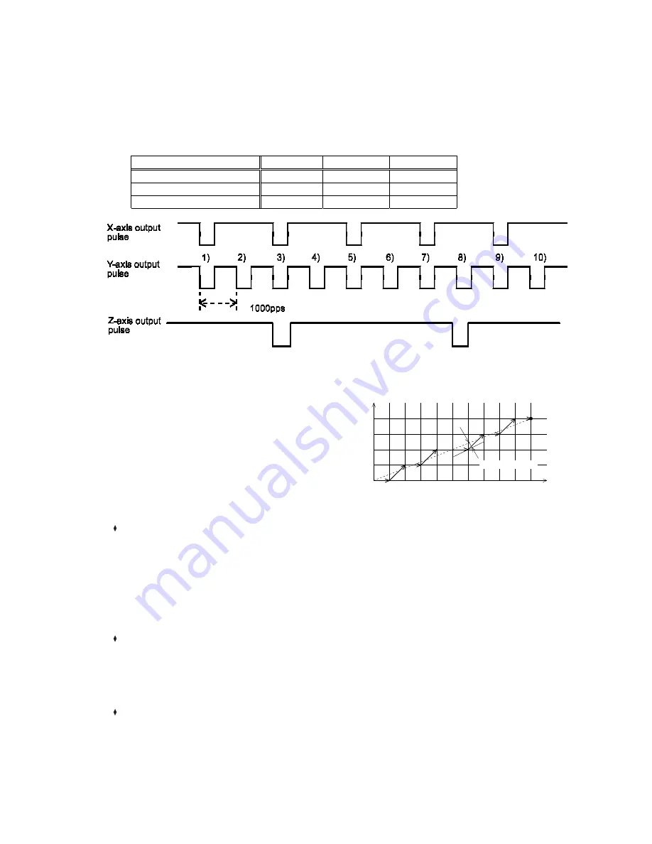
[Setting
example]
Use
the
settings
below
and
write
a
start
command
(0751h).
The
PCL
will
output
pulses
with
the
timing
shown
in
the
figure
below.
Entering
values
in
the
blank
items
will
not
affect
operation.
Setting
X
axis
Y
axis
Z
axis
MOD
63h
63h
63h
PRMV
value
5
10
2
Operation
speed
1000
pps
1000
pps
1000
pps
[Precision
of
linear
interpolation]
As
shown
in
the
figure
on
the
right,
linear
interpolation
executes
an
interpolation
from
the
current
coordinates
to
the
end
coordinates.
The
positional
precision
of
a
specified
line
during
linear
interpolation
will
be
±
0.5
LSB
throughout
the
interpolation
range.
"LSB"
refers
to
the
minimum
feed
unit
for
the
PRMV
register
setting.
It
corresponds
to
the
resolution
of
the
mechanical
system.
(distance
between
tick
marks
in
the
figure
on
the
right.)
9-6-3.
Operation
during
interpolation
Acceleration/deceleration
operations
In
addition
to
constant
speed
operation,
these
axes
can
accelerate/decelerate
(linear
acceleration
or
S-
curve),
and
a
ramp
down
point
with
an
automatic
setting
is
also
available.
However,
the
following
restrictions
apply:
1)
The
settings
for
MSDP
and
MADJ
in
the
PRMD
register
must
be
identical
for
all
the
axes
that
will
perform
an
interpolation.
2)
If
you
want
to
use
the
manual
setting
(MSDP
=
1)
for
the
ramp
down
point,
enter
the
value
for
the
longest
feed
axis
in
the
PRDP
registers
of
all
the
axes
that
will
perform
an
interpolation.
Error
stop
If
any
of
the
axes
performing
the
interpolation
stops
on
an
error,
the
other
axes
performing
an
interpolation
will
also
stop
by
the
CSTP
function
(simultaneous
stop
function).
Axes
that
did
not
encounter
an
error
will
show
ESSP
=
1
when
the
REST
register
is
read
(error
stop
cause).
This
allows
you
to
identify
the
axis
that
had
an
error.
SD
input
When
SD
input
is
enabled
(MSDE
(bit
8)
in
the
PRMD
register
is
set
to
1)
by
processing
the
CSD
terminal,
and
if
the
SD
input
turns
ON
either
of
the
axes,
both
axes
will
decelerate
or
decelerate
and
stop.
Y (Slave axis)
End coordinates
(10, 4)
X (Master axis)
4
3
2
1
0
0
5
10
±
0.5 LSB max
Summary of Contents for PCL6113
Page 1: ...User s Manual For PCL6113 6123 6143 Pulse Control LSI Nippon Pulse Motor Co Ltd...
Page 11: ...5 3 Terminal Assignment Diagram 3 1 PCL6113 3 2 PCL6123...
Page 20: ...14 5 Block Diagram...
Page 115: ...109 11 Stop timing by error...
Page 116: ...110 13 External Dimensions 13 1 PCL6113...
Page 117: ...111 13 2 PCL6123...
Page 118: ...112 13 3 PCL6143...


