-
22
-
6-5-4.
Reading
the
main
status
(MSTSW,
MSTSB)
Bit
Bit
name
Details
0
SSCM
Set
to
1
by
writing
a
start
command.
Set
to
0
when
the
operation
is
stopped.
1
SRUN
Set
to
1
by
the
start
pulse
output.
Set
to
0
when
the
operation
is
stopped.
2
SENI
Stop
interrupt
flag
When
IEND
in
RENV2
is
1,
the
PCL
turns
ON
the
INT
output
when
the
status
changes
from
operating
to
stop,
and
the
SENI
bit
becomes
1.
(After
the
main
status
is
read,
it
returns
to
0.)
When
IEND
is
set
to
0,
this
flag
will
always
be
0.
3
SEND
Set
to
0
by
writing
start
command.
Set
to
1
when
the
operation
is
stopped.
4
SERR
Set
to
1
when
an
error
interrupt
occurs.
Set
to
0
by
reading
the
RESET.
5
SINT
Set
to
1
when
an
error
interrupt
occurs.
Set
to
0
by
reading
the
RIST.
6
to
7
SSC0
to
1 Sequence
number
for
execution
or
stopping.
8
SCP1
Set
to
1
when
the
COMPARATOR
1
comparison
conditions
are
met.
9
SCP2
Set
to
1
when
the
COMPARATOR
2
comparison
conditions
are
met.
10
to
12
Not
defined
(always
0)
13
SEOR
When
a
positioning
override
cannot
be
executed
(reading
the
RMV
register
while
stopped),
this
signal
changes
to
1.
After
the
main
status
is
read,
it
changes
to
0.
14
SPRF
Set
to
1
when
the
pre-register
for
the
subsequent
operation
data
is
full.
15
Not
defined
(always
0)
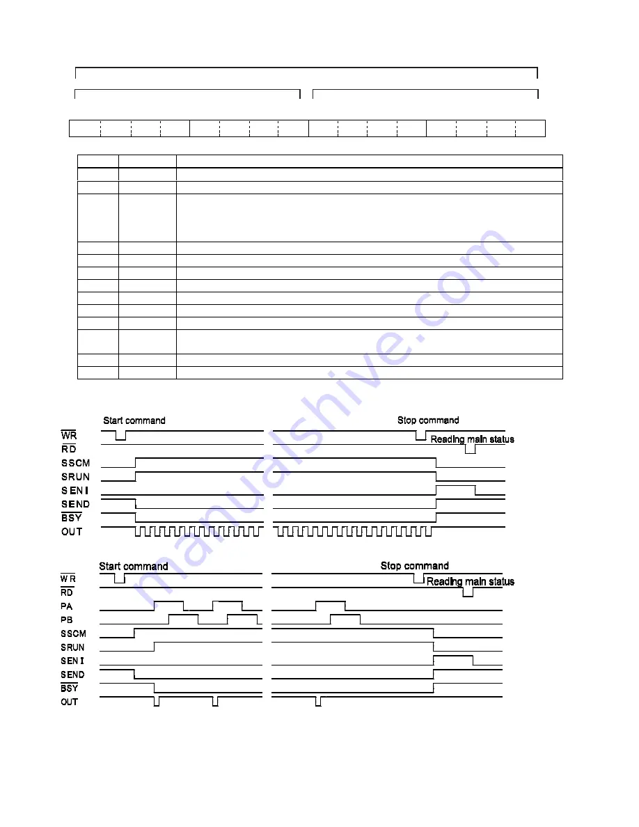
Status
change
timing
chart
1)
When
the
continuous
mode
(MOD=00h,
08h)
is
selected.
2)
When
the
PA/
PB
continuous
mode
(MOD=01h)
is
selected.
15
14
13
12
11
10
9
8
7
6
5
4
3
2
1
0
0
SEOR
0
0
0
0
SCP2
SPRF
SCP1 SSC1 SSC0 SINT SERR SEND SENI SRUN SSCM
MSTSB1
MSTSB0
MSTSW
Summary of Contents for PCL6113
Page 1: ...User s Manual For PCL6113 6123 6143 Pulse Control LSI Nippon Pulse Motor Co Ltd...
Page 11: ...5 3 Terminal Assignment Diagram 3 1 PCL6113 3 2 PCL6123...
Page 20: ...14 5 Block Diagram...
Page 115: ...109 11 Stop timing by error...
Page 116: ...110 13 External Dimensions 13 1 PCL6113...
Page 117: ...111 13 2 PCL6123...
Page 118: ...112 13 3 PCL6143...


