-
82
-
11-5-2.
ERC
signal
A
servomotor
delays
the
stop
until
the
deflection
counter
in
the
driver
reaches
zero,
even
after
command
pulses
have
stopped
being
delivered.
In
order
to
stop
the
servomotor
immediately,
the
deflection
counter
in
the
servo
driver
must
be
cleared.
This
LSI
can
output
a
signal
to
clear
the
deflection
counter
in
the
servo
driver.
This
signal
is
referred
to
as
an
"ERC
signal."
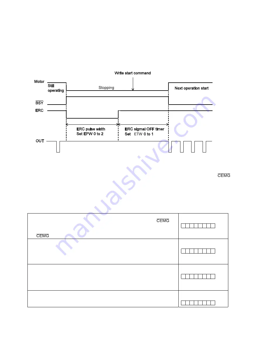
The
ERC
signal
is
output
as
one
shot
signal
or
a
logic
level
signal.
The
output
type
can
be
selected
by
setting
EPW
in
the
RENV1
register
(environment
setting
1).
If
an
interval
is
required
for
the
servo
driver
to
recover
after
turning
OFF
the
ERC
signal
(HIGH)
before
it
can
receive
new
command
pulses,
the
ETW
signal
OFF
timer
can
be
selected
by
setting
ETW
in
the
RENV1
register.
In
order
to
output
an
ERC
signal
at
the
completion
of
a
zero
return
operation,
set
EROR
(bit
11)
=
1
in
the
RENV1
register
(environment
setting
1)
to
make
the
ERC
signal
an
automatic
output.
For
details
about
ERC
signal
output
timing,
see
the
timing
waveform
in
section
9-5-1,
"Zero
return
operation."
In
order
to
output
an
ERC
signal
for
an
immediate
stop
based
on
the
EL
signal,
ALM
signal,
or
signal
input,
or
on
the
emergency
stop
command
(05h),
set
EROE
(bit
10)
=
1
in
the
RENV1
register,
and
set
automatic
output
for
the
ERC
signal.
(In
the
case
of
a
deceleration
stop,
the
ERC
signal
cannot
be
output,
even
when
set
for
automatic
output.)
The
ERC
signal
can
be
output
by
writing
an
ERC
output
command
(24h).
The
output
logic
of
the
ERC
signal
can
be
changed
by
setting
the
RENV1
register.
Read
the
RSTS
(extension
status)
register
to
monitor
the
ERC
signal.
Set
automatic
output
for
the
ERC
signal
<Set
EROE
(bit
10)
in
RENV1>
1:
Does
not
output
an
ERC
signal
when
stopped
by
EL,
ALM,
or
input.
1:
Automatically
outputs
an
ERC
signal
when
stopped
by
EL,
ALM,
or
input.
[RENV1]
(WRITE)
15
8
-
-
-
-
-
n
-
-
Set
automatic
output
for
the
ERC
signal
<Set
EROR
(bit
11)
in
RENV1>
0:
Does
not
output
an
ERC
signal
at
the
completion
of
a
zero
return
operation.
1:
Automatically
outputs
an
ERC
signal
at
the
completion
of
a
zero
return
operation.
[RENV1]
(WRITE)
15
8
-
-
-
-
n
-
-
-
Set
the
ERC
signal
output
width
<Set
EPW0
to
2
(bits
12
to
14)
in
RENV1>
000:
12
µ
sec
100:
13
msec
001:
102
µ
sec
101:
52
msec
010:
408
µ
sec
110:
104
msec
011:
1.6
msec
111:
Logic
level
output
[RENV1]
(WRITE)
15
8
-
n
n
n
-
-
-
-
Select
output
logic
for
the
ERC
signal
<Set
ERCL
(bit
15)
in
RENV1>
0:
Negative
logic
1:
Positive
logic
[RENV1]
(WRITE)
15
8
n
-
-
-
-
-
-
-
Summary of Contents for PCL6113
Page 1: ...User s Manual For PCL6113 6123 6143 Pulse Control LSI Nippon Pulse Motor Co Ltd...
Page 11: ...5 3 Terminal Assignment Diagram 3 1 PCL6113 3 2 PCL6123...
Page 20: ...14 5 Block Diagram...
Page 115: ...109 11 Stop timing by error...
Page 116: ...110 13 External Dimensions 13 1 PCL6113...
Page 117: ...111 13 2 PCL6123...
Page 118: ...112 13 3 PCL6143...


