-
87
-
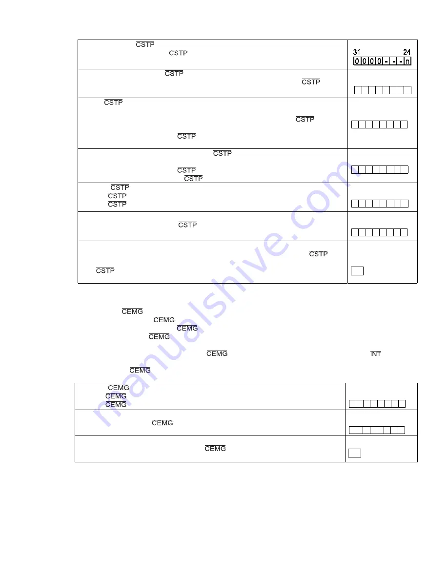
Setting
to
enable
input
<Set
MSPE
(bit
24)
in
PRMD>
1.
Enable
a
stop
from
the
input.
(Immediate
stop,
deceleration
stop)
[PRMD]
(WRITE)
Auto
output
setting
for
the
signal
<Set
to
MSPO
(bit
25)
in
the
PRMD>
1:
When
an
axis
stops
because
of
an
error,
the
PCL
will
output
the
signal.
(Output
signal
width:
8
reference
clock
cycles)
[PRMD]
(WRITE)
31
24
0
0
0
0
-
-
n
-
Set
the
to
output
a
signal
when
an
axis
is
stopped
by
a
command
<Set
CSP0
(bits
13)
in
RENV2>
1:
When
MSP0
=
1
in
the
PRMD
register,
the
PCL
will
output
the
signal
even
if
an
axis
is
stopped
by
a
command.
0:
The
PCL
will
not
output
a
signal
when
an
axis
is
stopped
by
a
command.
[RENV2]
(WRITE)
15
8
-
-
n
-
-
-
-
-
Specify
the
stop
method
to
use
when
the
signal
is
turned
ON.
<Set
STPM
(bit
19)
in
RENV1>
0:
Immediate
stop
when
the
signal
is
turned
ON.
1:
Deceleration
stop
when
the
signal
is
turned
ON.
[RENV1]
(WRITE)
23
16
-
-
-
-
n
-
-
-
Read
the
signal
<SSTP
(bit
6)
in
RSTS>
0:
The
signal
is
OFF
1:
The
signal
is
ON
[RSTS]
(READ)
7
0
-
n
-
-
-
-
-
-
Read
the
cause
of
an
error
input
<
ESSP
(bit
3)
in
REST>
1.
When
stopped
because
the
signal
turned
ON.
[REST]
(READ)
7
0
-
-
-
-
n
-
-
-
Simultaneous
stop
command
<CMSTP:
Operation
command>
Outputs
a
one
shot
pulse
of
8
reference
clock
cycles
in
length
from
the
terminal.
(The
terminal
is
bi-directional.
It
can
receive
signals
output
from
other
PCLs.)
[Operation
command]
07h
11-8.
Emergency
stop
This
LSI
has
a
input
terminal
for
use
as
an
emergency
stop
signal.
While
in
operation,
if
the
input
goes
LOW
or
if
you
write
an
emergency
stop
command,
all
the
axes
will
stop
immediately.
While
the
input
remains
LOW,
no
axis
can
be
operated.
The
logical
input
of
the
terminal
cannot
be
changed.
When
the
axes
are
stopped
because
the
input
was
turned
ON,
the
LSI
will
output
an
signal.
By
reading
the
REST
register,
the
cause
of
the
error
interruption
can
be
determined.
The
status
of
the
terminal
can
be
monitored
by
reading
the
REST
register
(extension
status).
Read
the
signal
<SEMG
(bit
7)
in
RSTS>
0:
The
signal
is
OFF
1:
The
signal
is
ON
[RSTS]
(READ)
7
0
n
-
-
-
-
-
-
-
Read
the
cause
of
an
error
interrupt
<ESEM
(bit
4)
in
REST>
1.
Stopped
when
the
signal
was
turned
ON.
[REST]
(READ)
7
0
-
-
-
n
-
-
-
-
Emergency
stop
command
<CMEMG:
Operation
command>
The
operation
is
the
same
as
when
a
signal
is
input.
[Operation
command]
05h
Note:
In
a
normal
stop
operation,
the
final
pulse
width
is
normal.
However,
in
an
emergency
stop
operation,
the
final
pulse
width
may
not
be
normal.
It
can
be
triangular.
Motor
drivers
do
not
recognize
triangle
shaped
pulses,
and
therefore
only
the
PCL
counter
may
count
this
pulse.
(Deviation
from
the
instructed
position
control).
Therefore,
after
an
emergency
stop,
you
must
perform
a
zero
return
to
match
the
instructed
position
with
the
mechanical
position.
Summary of Contents for PCL6113
Page 1: ...User s Manual For PCL6113 6123 6143 Pulse Control LSI Nippon Pulse Motor Co Ltd...
Page 11: ...5 3 Terminal Assignment Diagram 3 1 PCL6113 3 2 PCL6123...
Page 20: ...14 5 Block Diagram...
Page 115: ...109 11 Stop timing by error...
Page 116: ...110 13 External Dimensions 13 1 PCL6113...
Page 117: ...111 13 2 PCL6123...
Page 118: ...112 13 3 PCL6143...


