-
80
-
11-4-3.
ORG,
EZ
signals
These
signals
are
enabled
in
the
zero
return
modes.
When
the
input
filter
is
OFF
the
minimum
pulse
time
for
the
ORG
signal
is
2
reference
clock
cycles
(0.1
µ
s).
When
the
input
filter
is
ON,
the
PCL
will
not
respond
to
pulse
signals
shorter
than
the
specified
time.
In
addition,
the
ORG
signal
is
sampled
during
the
period
that
the
output
pulse
is
ON,
so
the
ORG
input
must
be
latched
ON
for
more
than
one
pulse.
The
input
logic
of
the
ORG
signal
and
EZ
signal
can
be
changed
using
the
RENV1
register
and
RENV
2
register.
The
ORG
terminal
status
can
be
monitored
by
reading
SSTSW
(sub
status).
The
EZ
terminal
status
can
be
monitored
by
reading
the
RSTS
register
(extension
status).
For
details
about
the
zero
return
operation
modes,
see
9-5,
"Zero
position
operation
mode."
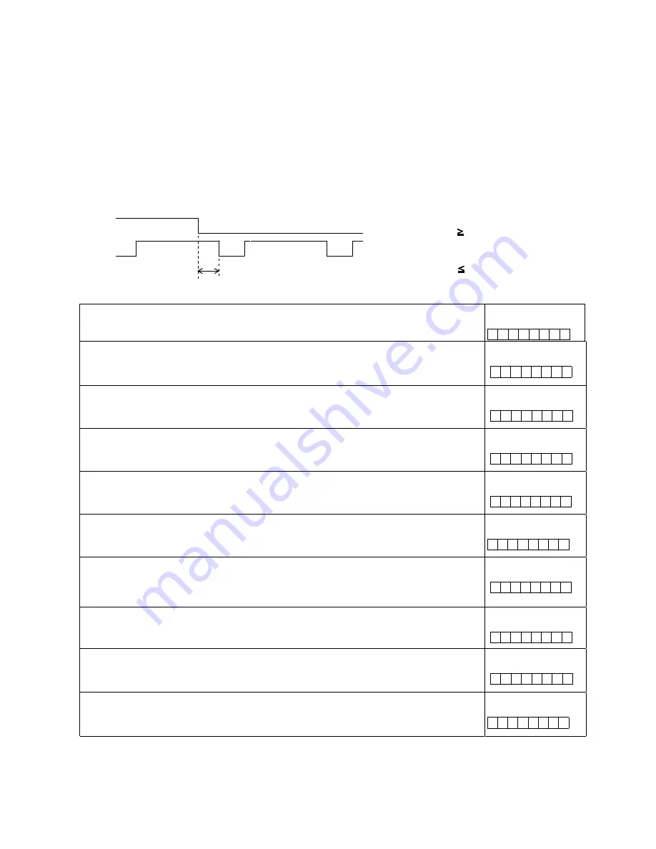
ORG
signal
and
EZ
signal
timing
(When
the
input
filter
is
OFF)
T
CLK:
:
Reference
clock
cycle
Enabling
the
ORG
and
EZ
signals
<Set
MOD
(bits
0
to
6)
in
PRMD>
001
0000:
Zero
return
in
the
positive
direction
010
1000:
Zero
return
in
the
negative
direction
[PRMD]
(WRITE)
7
0
0
n
n
n
n
n
n
n
Setting
the
zero
return
method
<Set
ORM
(bit
29)
in
RENV2>
0:
Use
only
the
ORG
input.
1:
Use
both
the
ORG
input
and
EZ
input.
[RENV2]
(WRITE)
31
24
-
-
n
-
-
-
-
-
Set
the
input
logic
for
the
ORG
signal
<Set
ORGL
(bit
7)
in
RENV1>
0:
Negative
logic
1:
Positive
logic
[RENV1]
(WRITE)
7
0
n
-
-
-
-
-
-
-
Set
the
ORG
input
filter
<FLTR
(bit
26)
in
RENV1>
1:
Apply
a
filter
to
the
±
EL,
SD,
ORG
ALM,
and
INP
input.
By
applying
a
filter,
pulses
shorter
than
the
FTM
set
value
are
ignored.
[RENV1]
(WRITE)
31
24
-
-
-
-
-
n
-
-
Setting
the
time
constant
for
the
input
filter
<Set
FTM
(bits
20,
21)
in
RENV1>
00:
3.2
µ
s
10:
200
µ
s
01:
25
µ
s
11:
1.6
ms
[RENV1]
(WRITE)
23
16
-
-
n
n
-
-
-
-
Read
the
ORG
signal
<SORG
(bit
14)
in
SSTSW>
0:
The
ORG
signal
is
OFF
1:
The
ORG
signal
is
ON
[SSTSW]
(READ)
15
8
-
n
-
-
-
-
-
-
Set
the
EZ
count
number
<Set
EZD0
to
3
(bits
24
to
27)
in
RENV2>
Set
the
zero
return
completion
condition
and
the
EZ
count
number
for
counting.
Specify
the
value
(the
number
to
count
to
ñ
1)
in
EZD0
to
3.
The
setting
range
is
0
to
15.
[RENV2]
(WRITE)
31
24
-
-
-
-
n
n
n
n
Specify
the
input
logic
of
the
EZ
signal
<Set
EZL
(bit
28)
in
RENV2>
0:
Falling
edge
1:
Rising
edge
[RENV2]
(WRITE)
31
24
-
-
-
n
-
-
-
-
Read
the
EZ
signal
<SEZ
(bit
10)
in
RSTS>
0:
The
EZ
signal
is
OFF
1:
The
EZ
signal
is
ON
[RSTS]
(READ)
15
8
-
-
-
-
-
n
-
-
Set
the
EZ
input
filter
<EINF
(bit
18)
in
RENV1>
1:
Apply
a
filter
to
the
EA,
EB,
EZ
input.
By
applying
a
filter,
input
signal
pulses
shorter
than
3
cycles
of
CLK
are
ignored.
[RENV1]
(WRITE)
23
16
-
-
-
-
-
n
-
-
ORG
EZ
t
(i)
When
t
2
x
T
CLK
,
counts.
(ii)
When
T
CLK
<
t
<
2
x
T
CLK
,
counting
is
undetermined.
(iii)
When
t
T
CLK
,
do
not
count.
Summary of Contents for PCL6113
Page 1: ...User s Manual For PCL6113 6123 6143 Pulse Control LSI Nippon Pulse Motor Co Ltd...
Page 11: ...5 3 Terminal Assignment Diagram 3 1 PCL6113 3 2 PCL6123...
Page 20: ...14 5 Block Diagram...
Page 115: ...109 11 Stop timing by error...
Page 116: ...110 13 External Dimensions 13 1 PCL6113...
Page 117: ...111 13 2 PCL6123...
Page 118: ...112 13 3 PCL6143...


