Main Bearings
General information
Service main bearings are available in standard size and 0.25
mm (0.0098 in.) undersize, and each of them has 5 kinds of
bearings differing in tolerance.
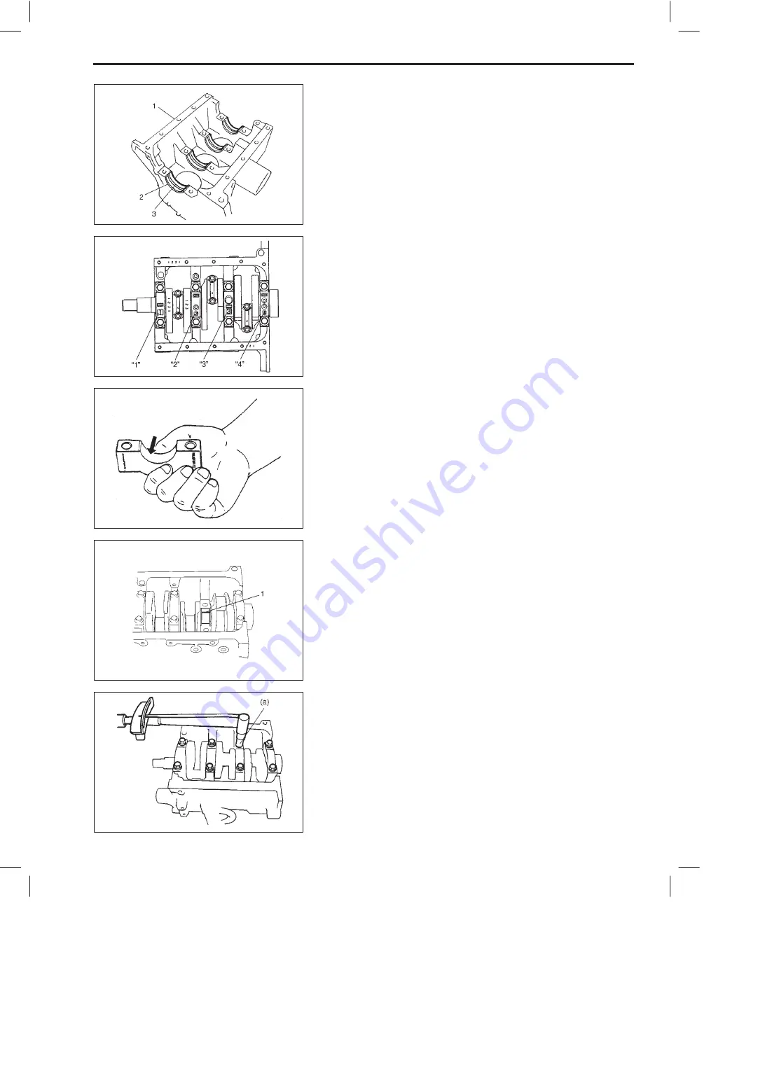
Upper half of bearing (2) has oil groove (3) as shown in figure.
Install this half with oil groove to cylinder block (1).
On each main bearing cap, arrow mark and number are em-
bossed as shown in figure.
When installing each bearing cap to cylinder block, point arrow
mark toward crankshaft pulley side and install each cap from
that side to flywheel side in ascending order of numbers “1”, “2”,
“3” and “4”. Tighten cap bolts to specified torque.
Inspection
Check bearings for pitting, scratches, wear or damage.
If any malcondition is found, replace both upper and lower halves.
Never replace one half without replacing the other half.
Main bearing clearance
Check clearance by using gaging plastic according to following
procedure.
1) Remove bearing caps.
2) Clean bearings and main journals.
3) Place a piece of gaging plastic (1) to full width of bearing (paral-
lel to crankshaft) on journal, avoiding oil hole.
4) Install bearing cap as previously outlined and evenly torque cap
bolts to specified torque.
Bearing cap must be torqued to specification in order to assure
proper reading of clearance.
Tightening Torque
(a): 47 N
.
m (4.7 kg-m, 34.0 lb-ft)
NOTE:
Do not rotate crankshaft while gaging plastic is installed.
ENGINE MECHANICAL (F8D ENGINE)
6A1-55


