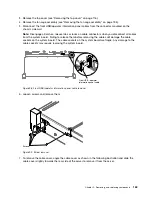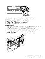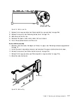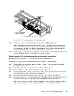
Front USB / operator
information panel cable
Figure 123. Cable connection
11. Replace the fan cage assembly (see “Replacing the fan cage assembly” on page 136).
12. Replace the top cover (see “Replacing the top cover” on page 118).
13. Slide the server into the rack.
14. Reconnect the power cords and any cables that you removed.
15. Turn on the peripheral devices and the server.
For the left EIA assembly
1. Read the safety information that begins on “Safety” on page v and “Removing and replacing guidelines”
2. Turn off the server and peripheral devices, and disconnect the power cord and all external cables.
3. Remove the top cover (see “Removing the top cover” on page 116).
4. Remove the fan cage assembly (see “Removing the fan cage assembly” on page 135).
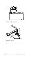
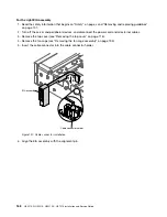
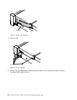
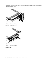
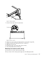
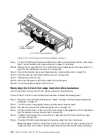
5. Route the cable into the slot.
EIA assembly
Figure 124. Cable routing
.
Removing, and replacing components
177
Summary of Contents for HX3510-G
Page 1: ...HX3510 G HX5510 HX5510 C HX7510 Installation and Service Guide Machine Type 8695 ...
Page 6: ...iv HX3510 G HX5510 HX5510 C HX7510 Installation and Service Guide ...
Page 62: ...50 HX3510 G HX5510 HX5510 C HX7510 Installation and Service Guide ...
Page 102: ...90 HX3510 G HX5510 HX5510 C HX7510 Installation and Service Guide ...
Page 112: ...100 HX3510 G HX5510 HX5510 C HX7510 Installation and Service Guide ...
Page 1222: ...1210 HX3510 G HX5510 HX5510 C HX7510 Installation and Service Guide ...
Page 1238: ...1226 HX3510 G HX5510 HX5510 C HX7510 Installation and Service Guide ...
Page 1239: ......
Page 1240: ......

