Step 6.
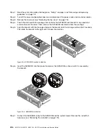
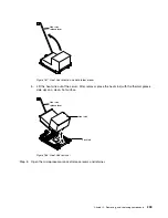
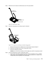
Rotate the heat sink retention module release lever to the open position.
Retainer bracket
Heat sink
release lever
Lock tab
Figure 176. Heat-sink lever rotation
Step 7.
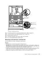
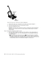
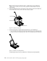
Open the microprocessor socket release levers and retainer:
1
3
2
Microprocessor
release levers
Figure 177. Microprocessor socket levers and retainer disengagement
a.
Identify which release lever is labeled as the first release lever to open and open it.
b.
Open the second release lever on the microprocessor socket.
c.
Open the microprocessor retainer.
Attention:
Do not touch the connectors on the microprocessor and the microprocessor socket.
Step 8.
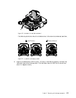
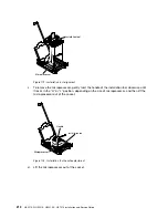
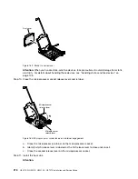
Install the microprocessor on the microprocessor socket:
a.
Touch the static-protective package that contains the new microprocessor to any
unpainted
on the chassis or any
unpainted
metal surface on any other grounded rack component; then,
carefully remove the microprocessor from the package.
.
Removing, and replacing components
215
Summary of Contents for HX3510-G
Page 1: ...HX3510 G HX5510 HX5510 C HX7510 Installation and Service Guide Machine Type 8695 ...
Page 6: ...iv HX3510 G HX5510 HX5510 C HX7510 Installation and Service Guide ...
Page 62: ...50 HX3510 G HX5510 HX5510 C HX7510 Installation and Service Guide ...
Page 102: ...90 HX3510 G HX5510 HX5510 C HX7510 Installation and Service Guide ...
Page 112: ...100 HX3510 G HX5510 HX5510 C HX7510 Installation and Service Guide ...
Page 1222: ...1210 HX3510 G HX5510 HX5510 C HX7510 Installation and Service Guide ...
Page 1238: ...1226 HX3510 G HX5510 HX5510 C HX7510 Installation and Service Guide ...
Page 1239: ......
Page 1240: ......


