


ML610Q421/ML610Q422/ML610421 User’s Manual
Chapter 24 RC Oscillation Type A/D Converter
24 – 8
24.3 Description of Operation
Counter A (RADCA0–2) is a 24-bit binary counter for counting the base clock (BSCLK), which is used as the standard
of time. Counter A can count up to 0FFFFFFH.
Counter B (RADCB0–2) is a 24-bit binary counter for counting the oscillator clock (RCCLK) of the RC oscillator
circuits. Counter B can count up to 0FFFFFFH.
Counters A and B are provided with overflow flags (OVFA and OVFB, respectively). Each overflow output results in
generation of an RC-ADC interrupt request signal (RADINT). Use the RADI bit of the RC-AC mode register
(RADMOD) to select whether to generate an overflow interrupt by an overflow on Counter A or Counter B: setting
RADI to “0” specifies Counter A overflow and setting it to “1” specifies Counter B overflow.
The RARUN bit of the RC-AD control register (RADCON) is used to start or stop RC-ADC conversion operation.
When RARUN is set to “0”, the oscillator circuits stop, so that counting will not be performed. When RARUN is set
to “1”, RC oscillation starts, when the RC oscillator clock (RCCLK) and the base clock (BSCLK) start counting
through Counter B and Counter A.
The RC oscillation section has a total of eight types of oscillation modes based on the two oscillator circuits of
RCOSC0 and RCOSC1, and mode selection is made by the RC-ADC mode register (RADMOD).
P30–34, P44–47, and P35 must be configured as their secondary function input or output when using 1) the RC
oscillator circuit RCOSC0, 2) the RC oscillator circuit RCOSC1, and 3) the RC monitor pin (RCM) that outputs RC
oscillation waveforms, respectively. For the configuration of the RC oscillator circuits, see Section 24.1.2,
“Configuration”; for the secondary functions of Port 3, see Chapter 20, “Port 3”; for the secondary functions of Port 4,
see Chapter 21, “Port 4”.
24.3.1 RC Oscillator Circuits
RC-ADC performs A/D conversion by converting the oscillation frequency ratio between a reference resistor (or
capacitor) and a resistive sensor (or capacitive sensor) such as a thermistor to digital data.
By making RC oscillation occur both on the reference side and on the sensor side with the reference capacitor the error
factor that the RS oscillator circuit itself is eliminated, thereby making it possible to perform the A/D conversion of the
characteristics of the sensor itself.
Also, by calculating the ratio between the oscillation frequency on the reference side and that on the sensor side and
then calculating the correlation between the calculated ratio and temperatures that the sensor characteristics have in
advance, a temperature can be obtained based on that calculated ratio.
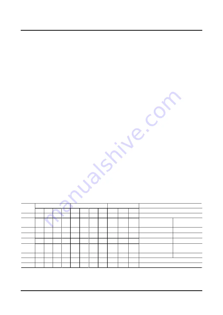
Table 24-1 lists the eight types of oscillation modes, one of which is selected by the RC-ADC mode register
(RADMOD) OM3–0 bits.
Table 24-1 Oscillation Modes from Which Selection Is Made by OM3–0 Bits
Mode
No.
RADMOD
RCOSC0 output pin
RCOSC1 output pin
Mode
OM3 OM2 OM1 OM0 RS0 RT0 RCT0 CS0 RS1 RT1 CS1
0
0
0
0
0
Z
Z
Z
Z
Z
Z
Z
IN0 external clock input mode
1
0
0
0
1
1/0
Z
Z
0/1
Z
Z
Z
RS0–CS0 oscillation
RCOSC0
oscillation mode
2
0
0
1
0
Z
1/0
Z
0/1
Z
Z
Z
RT0–CS0 oscillation
3
0
0
1
1
Z
Z
1/0
0/1
Z
Z
Z
RT
0-1
–CS0 oscillation
4
0
1
0
0
1/0
Z
0/1
Z
Z
Z
Z
RS0–CT0 oscillation
5
0
1
0
1
Z
Z
Z
Z
1/0
Z
0/1
RS1–CS1 oscillation
RCOSC1
oscillation mode
6
0
1
1
0
Z
Z
Z
Z
Z
1/0
0/1
RT1–CS1 oscillation
7
0
1
1
1
Z
Z
Z
Z
Z
Z
Z
IN1 external clock input mode
8
1
*
*
*
Z
Z
Z
Z
Z
Z
Z
(Setting prohibited)
Note)
*
: Indicates “arbitrary.”
Z
: Indicates high-impedance output.
1/0, 0/1
: Indicates active output.
(Setting prohibited)
: The oscillator clock is not supplied even by setting the RARUN bit to “1” or by
starting A/D conversion.
Summary of Contents for ML610421
Page 1: ...ML610Q421 ML610Q422 ML610421 User s Manual Issue Date Feb 9 2015 FEUL610Q421 06...
Page 15: ...Chapter 1 Overview...
Page 44: ...Chapter 2 CPU and Memory Space...
Page 49: ...Chapter 3 Reset Function...
Page 53: ...Chapter 4 MCU Control Function...
Page 69: ...Chapter 5 Interrupts INTs...
Page 93: ...Chapter 6 Clock Generation Circuit...
Page 110: ...Chapter 7 Time Base Counter...
Page 121: ...Chapter 8 Capture...
Page 129: ...Chapter 9 1 kHz Timer 1kHzTM...
Page 135: ...Chapter 10 Timers...
Page 160: ...Chapter 11 PWM...
Page 172: ...Chapter 12 Watchdog Timer...
Page 180: ...Chapter 13 Synchronous Serial Port...
Page 195: ...Chapter 14 UART...
Page 216: ...Chapter 15 I2 C Bus Interface...
Page 231: ...Chapter 16 NMI Pin...
Page 237: ...Chapter 17 Port 0...
Page 246: ...Chapter 18 Port 1...
Page 252: ...Chapter 19 Port 2...
Page 259: ...Chapter 20 Port 3...
Page 270: ...Chapter 21 Port 4...
Page 282: ...Chapter 22 Port A...
Page 290: ...Chapter 23 Melody Driver...
Page 304: ...Chapter 24 RC Oscillation Type A D Converter...
Page 327: ...Chapter 25 Successive Approximation Type A D Converter...
Page 338: ...Chapter 26 LCD Drivers...
Page 371: ...Chapter 27 Battery Level Detector...
Page 378: ...Chapter 28 Power Supply Circuit...
Page 381: ...Chapter 29 On Chip Debug Function...
Page 384: ...Appendixes...
Page 435: ...Revision History...