6-S21
M8540, M9540, WSM
FRONT AXLE
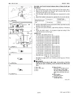
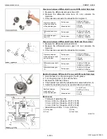
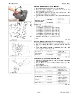
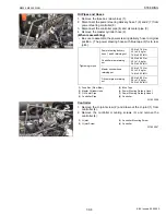
Backlash of Bevel Gear in Front Wheel Case
1. Set a dial indicator (lever type) on the shaft (Kingpin).
2. Move the shaft (Kingpin) by hand and measure the
circumferential play of the shaft.
3. Calculate the backlash from the ratio of the shaft diameter to the
gear diameter. (Backlash = Play x 2)
4. If the backlash exceeds the allowable limit, adjust with the shims
(1).
(Reference)
• Thickness of adjusting shims (1) :
0.1 mm (0.004 in.) [Code No.: 35533-44080]
0.2 mm (0.008 in.) [Code No.: 35533-44090]
0.4 mm (0.016 in.) [Code No.: 35533-44100]
0.8 mm (0.032 in.) [Code No.: 35533-44110]
1.0 mm (0.039 in.) [Code No.: 35533-44120]
1.2 mm (0.047 in.) [Code No.: 35533-44130]
• Standard size of shim (1) : 2.0 mm (0.079 in.)
W1021810
Backlash between Internal Gear and Planetary Gear
1. Set a dial indicator (lever type) on the tooth of the planetary gear.
2. Hold the planetary gear support and move only the planetary
gear.
3. If the measurement exceeds the allowable limit, check the
planetary gear and planetary shaft.
W1022069
Clearance between Planetary Gear and Shaft
1. Measure the planetary gear I.D. and the planetary gear shaft
O.D. (rubbing surface).
2. Measure the O.D. of two needles installed diagonally in the
needle bearing.
3. Calculate the clearance.
4. If the clearance exceeds the allowable limit, replace them.
W1021047
Backlash of bevel gear
in front wheel case
Factory spec.
0.20 to 0.30 mm
0.0079 to 0.0118 in.
Allowable limit
0.4 mm
0.016 in.
(1) Shim
Backlash between
internal gear and
planetary gear
Factory spec.
0.10 to 0.30 mm
0.0039 to 0.0118 in.
Allowable limit
0.5 mm
0.020 in.
Clearance between
planetary gear and shaft
Factory spec.
0.009 to 0.046 mm
0.00035 to 0.00181 in.
Allowable limit
0.3 mm
0.012 in.
Planetary gear I.D.
Factory spec.
33.009 to 33.025 mm
1.29957 to 1.30020 in.
Shaft O.D.
Factory spec.
24.991 to 25.000 mm
0.98390 to 0.98425 in.
Needle bearing O.D.
Factory spec.
3.994 to 4.000 mm
0.15724 to 0.15748 in.
KiSC issued 09, 2008 A
Summary of Contents for M9540
Page 1: ...M8540 M9540 WORKSHOP MANUAL TRACTOR KiSC issued 09 2008 A...
Page 8: ...6 M8540 M9540 WSM SAFETY INSTRUCTIONS KiSC issued 09 2008 A...
Page 9: ...7 M8540 M9540 WSM SAFETY INSTRUCTIONS KiSC issued 09 2008 A...
Page 10: ...8 M8540 M9540 WSM SAFETY INSTRUCTIONS Q CABIN Model KiSC issued 09 2008 A...
Page 11: ...9 M8540 M9540 WSM SAFETY INSTRUCTIONS KiSC issued 09 2008 A...
Page 12: ...10 M8540 M9540 WSM SAFETY INSTRUCTIONS KiSC issued 09 2008 A...
Page 16: ...14 M8540 M9540 WSM DIMENSIONS DIMENSIONS ROPS Model KiSC issued 09 2008 A...
Page 17: ...15 M8540 M9540 WSM DIMENSIONS CABIN Model KiSC issued 09 2008 A...
Page 18: ...G GENERAL KiSC issued 09 2008 A...
Page 103: ...1 ENGINE KiSC issued 09 2008 A...
Page 203: ...2 CLUTCH KiSC issued 09 2008 A...
Page 219: ...3 TRANSMISSION KiSC issued 09 2008 A...
Page 322: ...4 REAR AXLE KiSC issued 09 2008 A...
Page 323: ...CONTENTS MECHANISM 1 FEATURES 4 M1 KiSC issued 09 2008 A...
Page 336: ...5 BRAKES KiSC issued 09 2008 A...
Page 374: ...6 FRONT AXLE KiSC issued 09 2008 A...
Page 401: ...7 STEERING KiSC issued 09 2008 A...
Page 402: ...CONTENTS MECHANISM 1 STEERING MECHANISM 7 M1 2 STEERING CYLINDER 7 M2 KiSC issued 09 2008 A...
Page 420: ...8 HYDRAULIC SYSTEM KiSC issued 09 2008 A...
Page 473: ...9 ELECTRICAL SYSTEM KiSC issued 09 2008 A...
Page 554: ...10 CABIN KiSC issued 09 2008 A...

