G-39
M8540, M9540, WSM
G
GENERAL
[14] OTHERS
Bleeding Fuel System
Air must be removed:
1. When the fuel filter or lines are removed.
2. When water is drained from water separator.
3. When tank is completely empty.
4. After the tractor has not been used for a long period of time.
Q
Bleeding procedure is as follows:
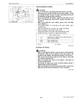
1. Fill the fuel tank with fuel, and open the fuel cock (1).
2. Pump the fuel pump knob (2) located on the top of the fuel filter.
The fuel pump knob will pump easily at first and with added
resistance as air is purged from the system. To make sure air is
completely purged, pinch the fuel overflow hose (3) with fingers,
if a pulsation is felt when the knob is pumped, then, no air
remains.
3. Set the hand throttle lever at the maximum speed position, turn
the key switch to start the engine, and then reset the throttle lever
at the mid speed (around 1500 min
−
1
(rpm)) position.
If engine does not start, try it several times at 30 second intervals.
4. Accelerate the engine to remove the small portion of air left in the
fuel system.
5. If air still remains and the engine stops, repeat the above steps.
IMPORTANT
Q
• Do not hold key switch at engine start position for more than
10 seconds continuously. If more engine cranking is
needed, try again after 30 seconds.
W1055254
Bleeding Brake System
1. Refer to “4. CHECKING, DISASSEMBLING AND SERVICING”
at “5. BRAKES” section.
W1079671
Draining Clutch Housing Water
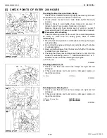
1. The tractor is equipped with drain plug (1) under the clutch
housing.
2. After operating in rain, snow or tractor has been washed, water
may get into the clutch housing.
3. Remove the drain plug (1) and drain the water, then install the
plug (1) again.
W1055587
Replacing Fuse (ROPS Model)
1. Refer to “4. CHECKING AND ADJUSTING” at “9. ELECTRICAL
SYSTEM” section.
W1029292
Replacing Fuse (CABIN Model)
1. Refer to “4. CHECKING AND ADJUSTING” at “9. ELECTRICAL
SYSTEM” section.
W1073497
(1) Fuel Cock
(2) Fuel Pump Knob
(3) Fuel Overflow Hose
(A) Close
(B) Open
(C) Up
(D) Down
(1) Drain Plug (Water)
KiSC issued 09, 2008 A
Summary of Contents for M9540
Page 1: ...M8540 M9540 WORKSHOP MANUAL TRACTOR KiSC issued 09 2008 A...
Page 8: ...6 M8540 M9540 WSM SAFETY INSTRUCTIONS KiSC issued 09 2008 A...
Page 9: ...7 M8540 M9540 WSM SAFETY INSTRUCTIONS KiSC issued 09 2008 A...
Page 10: ...8 M8540 M9540 WSM SAFETY INSTRUCTIONS Q CABIN Model KiSC issued 09 2008 A...
Page 11: ...9 M8540 M9540 WSM SAFETY INSTRUCTIONS KiSC issued 09 2008 A...
Page 12: ...10 M8540 M9540 WSM SAFETY INSTRUCTIONS KiSC issued 09 2008 A...
Page 16: ...14 M8540 M9540 WSM DIMENSIONS DIMENSIONS ROPS Model KiSC issued 09 2008 A...
Page 17: ...15 M8540 M9540 WSM DIMENSIONS CABIN Model KiSC issued 09 2008 A...
Page 18: ...G GENERAL KiSC issued 09 2008 A...
Page 103: ...1 ENGINE KiSC issued 09 2008 A...
Page 203: ...2 CLUTCH KiSC issued 09 2008 A...
Page 219: ...3 TRANSMISSION KiSC issued 09 2008 A...
Page 322: ...4 REAR AXLE KiSC issued 09 2008 A...
Page 323: ...CONTENTS MECHANISM 1 FEATURES 4 M1 KiSC issued 09 2008 A...
Page 336: ...5 BRAKES KiSC issued 09 2008 A...
Page 374: ...6 FRONT AXLE KiSC issued 09 2008 A...
Page 401: ...7 STEERING KiSC issued 09 2008 A...
Page 402: ...CONTENTS MECHANISM 1 STEERING MECHANISM 7 M1 2 STEERING CYLINDER 7 M2 KiSC issued 09 2008 A...
Page 420: ...8 HYDRAULIC SYSTEM KiSC issued 09 2008 A...
Page 473: ...9 ELECTRICAL SYSTEM KiSC issued 09 2008 A...
Page 554: ...10 CABIN KiSC issued 09 2008 A...


