


1-M14
M8540, M9540, WSM
ENGINE
W1015118
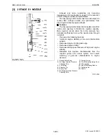
Q
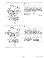
First opening pressure
The force of the high pressure fuel delivered by the injection pump acts to push the needle valve up. When this
force exceeds the set force of the first spring, the nozzle’s needle valve pushes the first pushrod up and the valve
opens. (First opening pressure is represented by point
E
in the left hand figure, and point
A
in the right hand figure.)
Q
Second opening pressure
When the first pushrod has been lifted through the pre-lift, it contacts the second pushrod. As the set force of the
second spring is acting on the second pushrod, the combined forces of both the first spring and the second spring then
act on the needle valve, which will not lift unless these forces are overcome.
When the high pressure fuel (ie, in-line pressure) overcomes the combined forces of the first and second springs,
the needle valve is again lifted and main injection can begin. (Second opening pressure is represented by point F in
the bottom left hand figure and B to C in the bottom right hand figure.)
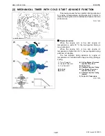
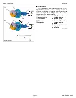
[4] INJECTION PUMP WITH F.S.P.
The fuel injection pump with F.S.P. (Fine Spill Port)
mechanism is equipped with two functions: speed timer
function and injection rate control function.
The former function works like this. As the rpm is low,
the injection timing gets delayed. This helps cut down on
NOx and operating noise.
The latter function serves to keep down the initial
injection rate and keep up the later injection rate, which
cuts down on NOx and PM as well.
W1014969
A-B : First Spring’s Set
Force
B-C-D : Combined Force of
First and Second
Springs
P1 : First Opening
Pressure
P2 : Second Opening
Pressure
L : Full Needle Valve Lift
I : Needle Valve Pre-lift
X1 : Cam Angle (°)
Y1 : Injection Rate (mm3/°)
X2 : Needle Valve Lift (mm)
Y2 : In-line Pressure
(1) Fine Spill Port (F.S.P.)
(2) Leaking Fuel at Initial Fuel
Pressure-Feed Stage
(3) Plunger Chamber
(4) Main Port
(5) F.S.P. Stroke
(6) Cylinder
(7) Plunger
KiSC issued 09, 2008 A
Summary of Contents for M9540
Page 1: ...M8540 M9540 WORKSHOP MANUAL TRACTOR KiSC issued 09 2008 A...
Page 8: ...6 M8540 M9540 WSM SAFETY INSTRUCTIONS KiSC issued 09 2008 A...
Page 9: ...7 M8540 M9540 WSM SAFETY INSTRUCTIONS KiSC issued 09 2008 A...
Page 10: ...8 M8540 M9540 WSM SAFETY INSTRUCTIONS Q CABIN Model KiSC issued 09 2008 A...
Page 11: ...9 M8540 M9540 WSM SAFETY INSTRUCTIONS KiSC issued 09 2008 A...
Page 12: ...10 M8540 M9540 WSM SAFETY INSTRUCTIONS KiSC issued 09 2008 A...
Page 16: ...14 M8540 M9540 WSM DIMENSIONS DIMENSIONS ROPS Model KiSC issued 09 2008 A...
Page 17: ...15 M8540 M9540 WSM DIMENSIONS CABIN Model KiSC issued 09 2008 A...
Page 18: ...G GENERAL KiSC issued 09 2008 A...
Page 103: ...1 ENGINE KiSC issued 09 2008 A...
Page 203: ...2 CLUTCH KiSC issued 09 2008 A...
Page 219: ...3 TRANSMISSION KiSC issued 09 2008 A...
Page 322: ...4 REAR AXLE KiSC issued 09 2008 A...
Page 323: ...CONTENTS MECHANISM 1 FEATURES 4 M1 KiSC issued 09 2008 A...
Page 336: ...5 BRAKES KiSC issued 09 2008 A...
Page 374: ...6 FRONT AXLE KiSC issued 09 2008 A...
Page 401: ...7 STEERING KiSC issued 09 2008 A...
Page 402: ...CONTENTS MECHANISM 1 STEERING MECHANISM 7 M1 2 STEERING CYLINDER 7 M2 KiSC issued 09 2008 A...
Page 420: ...8 HYDRAULIC SYSTEM KiSC issued 09 2008 A...
Page 473: ...9 ELECTRICAL SYSTEM KiSC issued 09 2008 A...
Page 554: ...10 CABIN KiSC issued 09 2008 A...