


6-S15
M8540, M9540, WSM
FRONT AXLE
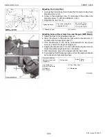
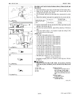
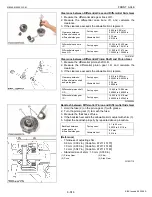
Backlash and Tooth Contact between Bevel Pinion Shaft and
Bevel Gear
1. Set a dial indicator (lever type) with its finger on the tooth surface.
2. Measure the backlash by fixing the bevel pinion shaft (2) and
moving the bevel gear (1) by hand.
3. If the backlash exceeds the allowable limit, adjust with the shim
(4).
4. Adjust the backlash properly by repeating the above procedures.
5. Apply red lead lightly over several teeth at three positions equally
spaced on the bevel gear (1).
6. Turn the bevel pinion shaft (2), against the periphery of the bevel
gear.
7. Check the tooth contact. If not proper, adjust according to the
instructions shown in the figure.
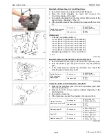
(Reference)
• Thickness of adjusting shims (3) :
0.1 mm (0.004 in.) [Code No.: 35533-44080]
0.2 mm (0.008 in.) [Code No.: 35533-44090]
0.4 mm (0.016 in.) [Code No.: 35533-44100]
0.8 mm (0.032 in.) [Code No.: 35533-44110]
1.0 mm (0.039 in.) [Code No.: 35533-44120]
1.2 mm (0.047 in.) [Code No.: 35533-44130]
• Thickness of adjusting shims (4) :
0.7 mm (0.028 in.) [Code No.: 3A151-32180]
0.8 mm (0.032 in.) [Code No.: 3A151-32130]
1.0 mm (0.039 in.) [Code No.: 3A151-32140]
1.2 mm (0.047 in.) [Code No.: 3A151-32150]
1.4 mm (0.551 in.) [Code No.: 3A151-32160]
2.3 mm (0.091 in.) [Code No.: 3A151-32170]
• Standard size of shim (3) : 0.5 mm (0.020 in.)
shim (4) : 1.2 mm (0.047 in.)
• Backlash changes per 0.1 mm (0.004 in.) shim : Approx. 0.05 mm
(0.002 in.)
IMPORTANT
Q
• Adjust the tooth contact with shims (3) and (4) so that the
spiral bevel pinion shaft may not contact with the differential
case.
W1018771
Backlash between bevel
gear and bevel pinion
shaft
Factory spec.
0.20 to 0.30 mm
0.0079 to 0.0118 in.
Allowable limit
0.4 mm
0.016 in.
(1) Bevel Gear
(2) Bevel Pinion Shaft
(3) Shim
(4) Shim
(A) Proper Contact :
More than 35 % red lead contact
area on the gear tooth surface.
The center of tooth contact at 1/3
of the entire width from the small
end.
(B) Deep Contact :
Decrease the shims.
(C) Shallow Contact :
Increase the shims.
KiSC issued 09, 2008 A
Summary of Contents for M9540
Page 1: ...M8540 M9540 WORKSHOP MANUAL TRACTOR KiSC issued 09 2008 A...
Page 8: ...6 M8540 M9540 WSM SAFETY INSTRUCTIONS KiSC issued 09 2008 A...
Page 9: ...7 M8540 M9540 WSM SAFETY INSTRUCTIONS KiSC issued 09 2008 A...
Page 10: ...8 M8540 M9540 WSM SAFETY INSTRUCTIONS Q CABIN Model KiSC issued 09 2008 A...
Page 11: ...9 M8540 M9540 WSM SAFETY INSTRUCTIONS KiSC issued 09 2008 A...
Page 12: ...10 M8540 M9540 WSM SAFETY INSTRUCTIONS KiSC issued 09 2008 A...
Page 16: ...14 M8540 M9540 WSM DIMENSIONS DIMENSIONS ROPS Model KiSC issued 09 2008 A...
Page 17: ...15 M8540 M9540 WSM DIMENSIONS CABIN Model KiSC issued 09 2008 A...
Page 18: ...G GENERAL KiSC issued 09 2008 A...
Page 103: ...1 ENGINE KiSC issued 09 2008 A...
Page 203: ...2 CLUTCH KiSC issued 09 2008 A...
Page 219: ...3 TRANSMISSION KiSC issued 09 2008 A...
Page 322: ...4 REAR AXLE KiSC issued 09 2008 A...
Page 323: ...CONTENTS MECHANISM 1 FEATURES 4 M1 KiSC issued 09 2008 A...
Page 336: ...5 BRAKES KiSC issued 09 2008 A...
Page 374: ...6 FRONT AXLE KiSC issued 09 2008 A...
Page 401: ...7 STEERING KiSC issued 09 2008 A...
Page 402: ...CONTENTS MECHANISM 1 STEERING MECHANISM 7 M1 2 STEERING CYLINDER 7 M2 KiSC issued 09 2008 A...
Page 420: ...8 HYDRAULIC SYSTEM KiSC issued 09 2008 A...
Page 473: ...9 ELECTRICAL SYSTEM KiSC issued 09 2008 A...
Page 554: ...10 CABIN KiSC issued 09 2008 A...