


5-S5
M8540, M9540, WSM
BRAKES
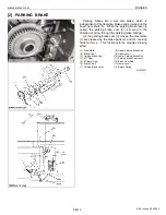
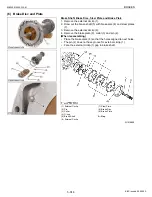
2) Brake Pedal Stroke
1. Disengage the brake pedal lock (2).
2. Depress the brake pedal several time.
3. Step on either side brake pedal and measure the level difference
(pedal stroke) between right and left pedals.
4. Do the same for the other side.
5. If the pedal stroke (
L
) exceeds the factory specification, check
the air bleeding, master cylinder, equalizer or brake case.
W1010823
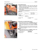
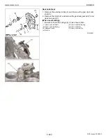
3) Equalizer Working Level (Anti-imbalance device)
1. Gently step on both the right and left pedals at once.
2. Further step on the right pedal (the left pedal slightly rises itself)
and measure the level difference between the pedals.
3. Do the same for left pedal.
4. If the measurement is not within the factory specification, check
the equalizer (2).
W1011041
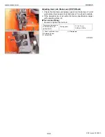
Brake Test
1. Remove the bleeder (1) from brake case and set the hydraulic
brake adaptor (refer to “8. SPECIAL TOOLS” at “G. GENERAL”
section), joint (Code No. 07916-50401), cable (Code No. 07916-
50331) and pressure gauge (Code No. 07916-52961).
2. Set the pedal fixing plate between the pedal and pedal stopper
after depressing the brake pedal to reach the pressure between
2.94 to 3.24 MPa (30 to 33 kgf/cm
2
, 426.7 to 469.4 psi).
3. Read the pressure
P
after one minute.
4. After reading the pressure
P
, wait another five minutes to read
the pressure
P’
and check the pressure drop. The pressure drop
should be within
P
x 0.1 MPa (
P
x 0.1 kgf/cm
2
,
P
x 0.1 psi).
5. If the pressure drop is too big, attach the pressure gauge to
equalizer (brake pipe rear end) and master cylinder (brake pipe
front end) to find out the problem area.
CAUTION
• If the air is in the master cylinder, brake pipe and case bleed
the air completely.
W1011229
Brake pedal stroke (
L
)
(each pedal)
Factory spec.
100 mm
3.9 in.
(1) Brake Pedal L.H.
(2) Brake Pedal Lock
(3) Brake Pedal R.H.
L : Pedal Stroke
[A] ROPS Model
[B] CABIN Model
Level difference
between both pedals
Factory spec.
Over 5 mm
0.2 in.
(1) Master Cylinder
(2) Equalizer
(1) Bleeder
KiSC issued 09, 2008 A
Summary of Contents for M9540
Page 1: ...M8540 M9540 WORKSHOP MANUAL TRACTOR KiSC issued 09 2008 A...
Page 8: ...6 M8540 M9540 WSM SAFETY INSTRUCTIONS KiSC issued 09 2008 A...
Page 9: ...7 M8540 M9540 WSM SAFETY INSTRUCTIONS KiSC issued 09 2008 A...
Page 10: ...8 M8540 M9540 WSM SAFETY INSTRUCTIONS Q CABIN Model KiSC issued 09 2008 A...
Page 11: ...9 M8540 M9540 WSM SAFETY INSTRUCTIONS KiSC issued 09 2008 A...
Page 12: ...10 M8540 M9540 WSM SAFETY INSTRUCTIONS KiSC issued 09 2008 A...
Page 16: ...14 M8540 M9540 WSM DIMENSIONS DIMENSIONS ROPS Model KiSC issued 09 2008 A...
Page 17: ...15 M8540 M9540 WSM DIMENSIONS CABIN Model KiSC issued 09 2008 A...
Page 18: ...G GENERAL KiSC issued 09 2008 A...
Page 103: ...1 ENGINE KiSC issued 09 2008 A...
Page 203: ...2 CLUTCH KiSC issued 09 2008 A...
Page 219: ...3 TRANSMISSION KiSC issued 09 2008 A...
Page 322: ...4 REAR AXLE KiSC issued 09 2008 A...
Page 323: ...CONTENTS MECHANISM 1 FEATURES 4 M1 KiSC issued 09 2008 A...
Page 336: ...5 BRAKES KiSC issued 09 2008 A...
Page 374: ...6 FRONT AXLE KiSC issued 09 2008 A...
Page 401: ...7 STEERING KiSC issued 09 2008 A...
Page 402: ...CONTENTS MECHANISM 1 STEERING MECHANISM 7 M1 2 STEERING CYLINDER 7 M2 KiSC issued 09 2008 A...
Page 420: ...8 HYDRAULIC SYSTEM KiSC issued 09 2008 A...
Page 473: ...9 ELECTRICAL SYSTEM KiSC issued 09 2008 A...
Page 554: ...10 CABIN KiSC issued 09 2008 A...