1-S77
M8540, M9540, WSM
ENGINE
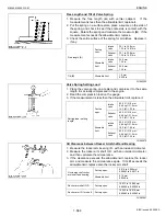
Oil Clearance between Crankshaft Journal and Crankshaft
Bearing
1. Clean the crankshaft journal and crankshaft bearing.
2. Put a strip of press gauge on the center of the journal.
IMPORTANT
Q
• Never insert the press gauge into the oil hole of the journal.
3. Install the main bearing case and tighten the screws to the
specified torque, and remove the cases again.
4. Measure the amount of the flattening with the scale and get the
oil clearance.
5. If the clearance exceeds the allowable limit, replace the
crankshaft bearing.
(Reference)
• Undersize dimensions of crankshaft journal.
W1069159
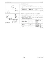
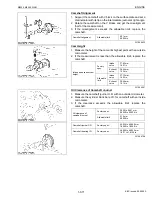
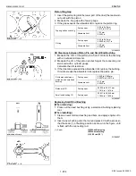
Replacing Crankshaft Sleeve
1. Remove the used crankshaft sleeve (2).
2. Set the sleeve guide (3) to the crankshaft (1).
3. Heat a new sleeve to a temperature between 150 to 200
°
C (302
to 392
°
F), and fix the sleeve to the crankshaft as shown in figure.
4. Press fit the sleeve using the auxiliary socket for pushing (4).
NOTE
Q
• Mount the sleeve with its largely chamfered surface facing
outward.
W1069911
Crankshaft journal O.D.
Factory spec.
74.977 to 74.990 mm
2.9519 to 2.9523 in.
Oil clearance between
crankshaft journal and
crankshaft bearing
Factory spec.
0.018 to 0.062 mm
0.00071 to 0.0024 in.
Allowable limit
0.20 mm
0.0079 in.
Undersize
0.2 mm
0.008 in.
0.4 mm
0.016 in.
Dimension
A
2.8 to 3.2 mm radius
0.11 to 0.12 in. radius
2.8 to 3.2 mm radius
0.11 to 0.12 in. radius
*Dimension
B
1.0 to 1.5 mm relief
0.040 to 0.059 in. relief
1.0 to 1.5 mm relief
0.040 to 0.059 in. relief
Dimension
C
74.777 to 74.790 mm dia.
2.9440 to 2.9444 in. dia.
74.577 to 74.590 mm dia.
2.9361 to 2.9366 in. dia.
(0.8-S)
The crankshaft journal must be fine-finished to higher than
∇∇∇∇.
*Holes to be de-burred and edges rounded with 1.0 to 1.5 mm
(0.040 to 0.059 in.) relief.
(1) Crankshaft
(2) Crankshaft Sleeve
(3) Sleeve Guide
(4) Auxiliary Socket for Pushing
KiSC issued 09, 2008 A
Summary of Contents for M9540
Page 1: ...M8540 M9540 WORKSHOP MANUAL TRACTOR KiSC issued 09 2008 A...
Page 8: ...6 M8540 M9540 WSM SAFETY INSTRUCTIONS KiSC issued 09 2008 A...
Page 9: ...7 M8540 M9540 WSM SAFETY INSTRUCTIONS KiSC issued 09 2008 A...
Page 10: ...8 M8540 M9540 WSM SAFETY INSTRUCTIONS Q CABIN Model KiSC issued 09 2008 A...
Page 11: ...9 M8540 M9540 WSM SAFETY INSTRUCTIONS KiSC issued 09 2008 A...
Page 12: ...10 M8540 M9540 WSM SAFETY INSTRUCTIONS KiSC issued 09 2008 A...
Page 16: ...14 M8540 M9540 WSM DIMENSIONS DIMENSIONS ROPS Model KiSC issued 09 2008 A...
Page 17: ...15 M8540 M9540 WSM DIMENSIONS CABIN Model KiSC issued 09 2008 A...
Page 18: ...G GENERAL KiSC issued 09 2008 A...
Page 103: ...1 ENGINE KiSC issued 09 2008 A...
Page 203: ...2 CLUTCH KiSC issued 09 2008 A...
Page 219: ...3 TRANSMISSION KiSC issued 09 2008 A...
Page 322: ...4 REAR AXLE KiSC issued 09 2008 A...
Page 323: ...CONTENTS MECHANISM 1 FEATURES 4 M1 KiSC issued 09 2008 A...
Page 336: ...5 BRAKES KiSC issued 09 2008 A...
Page 374: ...6 FRONT AXLE KiSC issued 09 2008 A...
Page 401: ...7 STEERING KiSC issued 09 2008 A...
Page 402: ...CONTENTS MECHANISM 1 STEERING MECHANISM 7 M1 2 STEERING CYLINDER 7 M2 KiSC issued 09 2008 A...
Page 420: ...8 HYDRAULIC SYSTEM KiSC issued 09 2008 A...
Page 473: ...9 ELECTRICAL SYSTEM KiSC issued 09 2008 A...
Page 554: ...10 CABIN KiSC issued 09 2008 A...


