


7-S13
M8540, M9540, WSM
STEERING
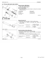
Grand Seal, Needle Bearing, Sleeve and Spool
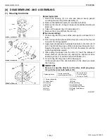
1. Remove the retaining ring (1) with a screw driver.
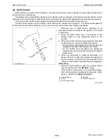
2. Hold the control valve unit vertically and spool and sleeve align
the cross pin parallels to flat side of housing (flow priority valve
mounting side), the cross pin is visible through open end of spool.
3. At this time, take care so as not to allow the cross pin to be caught
in the groove of the housing. If the cross pin is caught, adjust its
position with a fingertip.
4. Push the spool and sleeve to the allow direction and remove the
seal grand bushing (3) with dust seal (2) and quad ring seal (5).
5. Remove the O-ring (4) from the housing (12).
6. Remove the dust seal from the seal grand bushing (3).
7. Remove the O-ring (4).
(When reassembling)
• Replace O-ring with new one.
Apply transmission oil to the dust seal, quad ring seal and O-ring.
8. Remove the quad ring seal (5) from the sleeve (9).
9. Remove the bearing races and needle bearing from valve
assembly.
(When reassembling)
• Apply transmission oil to the bearing races and needle bearing.
10.Draw out the sleeve (9) and spool (11) assembly from the gerotor
side, with the port surface of the housing downward. At this time,
take care so as not to allow the dowel pin to be caught in the
groove of the housing (12). If the dowel pin is caught, adjust its
position with a fingertip and draw out the sleeve and spool
assembly slowly.
IMPORTANT
Q
• As the clearance between the housing and sleeve is very
narrow, do not forcibly draw out the sleeve.
(When reassembling)
• When fitting the sleeve (9) and spool (11) assembly into the
housing (12), apply clean transmission oil to the assembly and
then insert it while turning it slowly, taking care so that the parts
are not inclined. Also, pay attention to the dowel pin so that it is
not caught in the housing grooves. If the pin is caught, adjust its
position with a fingertip.
W1015723
(1) Retaining Ring
(2) Dust Seal
(3) Seal Grand Bushing
(4) O-ring
(5) Quad Ring Seal
(6) Bearing Race
(7) Needle Bearing
(8) Pin
(9) Sleeve
(10) Centering Spring
(11) Spool
(12) Housing
KiSC issued 09, 2008 A
Summary of Contents for M9540
Page 1: ...M8540 M9540 WORKSHOP MANUAL TRACTOR KiSC issued 09 2008 A...
Page 8: ...6 M8540 M9540 WSM SAFETY INSTRUCTIONS KiSC issued 09 2008 A...
Page 9: ...7 M8540 M9540 WSM SAFETY INSTRUCTIONS KiSC issued 09 2008 A...
Page 10: ...8 M8540 M9540 WSM SAFETY INSTRUCTIONS Q CABIN Model KiSC issued 09 2008 A...
Page 11: ...9 M8540 M9540 WSM SAFETY INSTRUCTIONS KiSC issued 09 2008 A...
Page 12: ...10 M8540 M9540 WSM SAFETY INSTRUCTIONS KiSC issued 09 2008 A...
Page 16: ...14 M8540 M9540 WSM DIMENSIONS DIMENSIONS ROPS Model KiSC issued 09 2008 A...
Page 17: ...15 M8540 M9540 WSM DIMENSIONS CABIN Model KiSC issued 09 2008 A...
Page 18: ...G GENERAL KiSC issued 09 2008 A...
Page 103: ...1 ENGINE KiSC issued 09 2008 A...
Page 203: ...2 CLUTCH KiSC issued 09 2008 A...
Page 219: ...3 TRANSMISSION KiSC issued 09 2008 A...
Page 322: ...4 REAR AXLE KiSC issued 09 2008 A...
Page 323: ...CONTENTS MECHANISM 1 FEATURES 4 M1 KiSC issued 09 2008 A...
Page 336: ...5 BRAKES KiSC issued 09 2008 A...
Page 374: ...6 FRONT AXLE KiSC issued 09 2008 A...
Page 401: ...7 STEERING KiSC issued 09 2008 A...
Page 402: ...CONTENTS MECHANISM 1 STEERING MECHANISM 7 M1 2 STEERING CYLINDER 7 M2 KiSC issued 09 2008 A...
Page 420: ...8 HYDRAULIC SYSTEM KiSC issued 09 2008 A...
Page 473: ...9 ELECTRICAL SYSTEM KiSC issued 09 2008 A...
Page 554: ...10 CABIN KiSC issued 09 2008 A...