


8-M11
M8540, M9540, WSM
HYDRAULIC SYSTEM
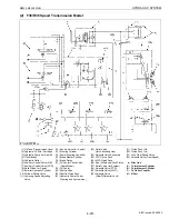
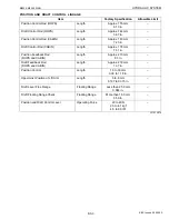
(2) Draft Control
Draft control is a system which maintains a constant traction load, and is suited for the work which needs heavy
traction load such as plowing.
The implement is automatically raised when its traction load is increased, and lowers when the traction load is
decreased. By maintaining a constant load level, it prevents the tractor from slipping and being loaded excessively.
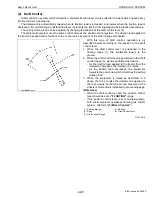
The setting traction load can be adjusted by changing the position of the draft control lever (5).
The draft control system uses the same control valve as the position control system. The traction load applied to
the tractor is sensed and is fed back to the control valve by means of the other linkage mechanism.
With this type of draft control, operation is as
described below according to the position of the draft
control lever.
1. When the draft control lever is positioned in the
floating range (1), the implement lowers to the
ground.
2. When the draft control lever is positioned in the draft
control range (3), work is performed as follows.
- As the traction load applied to the tractor from the
implement increases, the implement is raised.
- As the traction load decreases, the implement
lowers to the position at which it matches the setting
traction load.
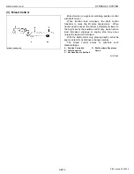
3. When the implement is raised as described in 2
above, the force to raise the implement is applied to
the rear wheels so that the ground pressure of the
wheels is momentarily increased to prevent slippage.
(Reference)
• When the draft control is used, the position control
lever should be set at
“FLOATING”
range.
• If the position control lever is set at working range,
both control systems operate performing mix control
system. (Refer to
“(3) Mixed Control”
.)
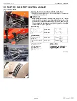
W1016418
(1) Floating Range
(2) Deep
(3) Draft Control Range
(4) Shallow
(5) Draft Control Lever
KiSC issued 09, 2008 A
Summary of Contents for M9540
Page 1: ...M8540 M9540 WORKSHOP MANUAL TRACTOR KiSC issued 09 2008 A...
Page 8: ...6 M8540 M9540 WSM SAFETY INSTRUCTIONS KiSC issued 09 2008 A...
Page 9: ...7 M8540 M9540 WSM SAFETY INSTRUCTIONS KiSC issued 09 2008 A...
Page 10: ...8 M8540 M9540 WSM SAFETY INSTRUCTIONS Q CABIN Model KiSC issued 09 2008 A...
Page 11: ...9 M8540 M9540 WSM SAFETY INSTRUCTIONS KiSC issued 09 2008 A...
Page 12: ...10 M8540 M9540 WSM SAFETY INSTRUCTIONS KiSC issued 09 2008 A...
Page 16: ...14 M8540 M9540 WSM DIMENSIONS DIMENSIONS ROPS Model KiSC issued 09 2008 A...
Page 17: ...15 M8540 M9540 WSM DIMENSIONS CABIN Model KiSC issued 09 2008 A...
Page 18: ...G GENERAL KiSC issued 09 2008 A...
Page 103: ...1 ENGINE KiSC issued 09 2008 A...
Page 203: ...2 CLUTCH KiSC issued 09 2008 A...
Page 219: ...3 TRANSMISSION KiSC issued 09 2008 A...
Page 322: ...4 REAR AXLE KiSC issued 09 2008 A...
Page 323: ...CONTENTS MECHANISM 1 FEATURES 4 M1 KiSC issued 09 2008 A...
Page 336: ...5 BRAKES KiSC issued 09 2008 A...
Page 374: ...6 FRONT AXLE KiSC issued 09 2008 A...
Page 401: ...7 STEERING KiSC issued 09 2008 A...
Page 402: ...CONTENTS MECHANISM 1 STEERING MECHANISM 7 M1 2 STEERING CYLINDER 7 M2 KiSC issued 09 2008 A...
Page 420: ...8 HYDRAULIC SYSTEM KiSC issued 09 2008 A...
Page 473: ...9 ELECTRICAL SYSTEM KiSC issued 09 2008 A...
Page 554: ...10 CABIN KiSC issued 09 2008 A...