1-S54
M8540, M9540, WSM
ENGINE
Installing Procedure of Injection Pump Assembly (Continued)
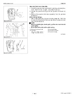
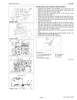
1. Move the stop lever (8) and visually check to see if the fuel
injection pump control rack comes smoothly back to the start
position by the counter force of the start spring.
2. If the control rack fails to move back smoothly, remove the start
spring and the anti-rotation nut, take the above steps from 2 of
the former page again.
3. Finally fit the sight cover and the stop solenoid back into place.
W1069772
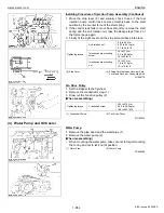
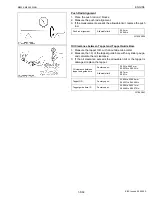
Fan Drive Pulley
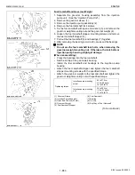
1. Set the stopper to the flywheel.
2. Remove the crankshaft screw (1).
3. Draw out the fan drive pulley (2).
(When reassembling)
W1185033
(4) Water Pump and Oil Cooler
Water Pump
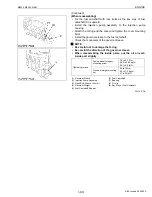
1. Remove the pipe band and the water pipe (1).
2. Remove the water pump (2).
(When reassembling)
• When mounting the water pump, take care not to forget mounting
the O-ring and not to let it out of position.
W1064806
Tightening torque
Anti-rotation nut
2.8 to 4.0 N·m
0.29 to 0.41 kgf·m
2.1 to 3.0 lbf·ft
Injection pump mounting
screw
24 to 27 N·m
2.4 to 2.8 kgf·m
18 to 20 lbf·ft
Injection pump mounting
nut
18 to 20 N·m
1.8 to 2.1 kgf·m
13 to 15 lbf·ft
(8) Stop Lever
(9) Sliding Point between Governor Fork
Lever and Governor Connecting Rod
Tightening torque
Crankshaft screw
255 to 274 N·m
26.0 to 28.0 kgf·m
188 to 202 lbf·ft
(1) Crankshaft Screw
(2) Fan Drive Pulley
(1) Water Pipe
(2) Water Pump
KiSC issued 09, 2008 A
Summary of Contents for M9540
Page 1: ...M8540 M9540 WORKSHOP MANUAL TRACTOR KiSC issued 09 2008 A...
Page 8: ...6 M8540 M9540 WSM SAFETY INSTRUCTIONS KiSC issued 09 2008 A...
Page 9: ...7 M8540 M9540 WSM SAFETY INSTRUCTIONS KiSC issued 09 2008 A...
Page 10: ...8 M8540 M9540 WSM SAFETY INSTRUCTIONS Q CABIN Model KiSC issued 09 2008 A...
Page 11: ...9 M8540 M9540 WSM SAFETY INSTRUCTIONS KiSC issued 09 2008 A...
Page 12: ...10 M8540 M9540 WSM SAFETY INSTRUCTIONS KiSC issued 09 2008 A...
Page 16: ...14 M8540 M9540 WSM DIMENSIONS DIMENSIONS ROPS Model KiSC issued 09 2008 A...
Page 17: ...15 M8540 M9540 WSM DIMENSIONS CABIN Model KiSC issued 09 2008 A...
Page 18: ...G GENERAL KiSC issued 09 2008 A...
Page 103: ...1 ENGINE KiSC issued 09 2008 A...
Page 203: ...2 CLUTCH KiSC issued 09 2008 A...
Page 219: ...3 TRANSMISSION KiSC issued 09 2008 A...
Page 322: ...4 REAR AXLE KiSC issued 09 2008 A...
Page 323: ...CONTENTS MECHANISM 1 FEATURES 4 M1 KiSC issued 09 2008 A...
Page 336: ...5 BRAKES KiSC issued 09 2008 A...
Page 374: ...6 FRONT AXLE KiSC issued 09 2008 A...
Page 401: ...7 STEERING KiSC issued 09 2008 A...
Page 402: ...CONTENTS MECHANISM 1 STEERING MECHANISM 7 M1 2 STEERING CYLINDER 7 M2 KiSC issued 09 2008 A...
Page 420: ...8 HYDRAULIC SYSTEM KiSC issued 09 2008 A...
Page 473: ...9 ELECTRICAL SYSTEM KiSC issued 09 2008 A...
Page 554: ...10 CABIN KiSC issued 09 2008 A...


