


1-S12
M8540, M9540, WSM
ENGINE
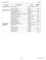
3. TIGHTENING TORQUES
Tightening torques of screws, bolts and nuts on the table below are especially specified.
(For general use screws, bolts and nuts : Refer to “5. TIGHTENING TORQUES” at “G. GENERAL” section.)
NOTE
Q
• For “*” marked screws, bolts and nuts on the table, apply engine oil to their threads and seats before
tightening.
W1013236
Item
N·m
kgf·m
lbf·ft
Nozzle holder clamp nut
18 to 20
1.8 to 2.1
13 to 15
Overflow pipe assembly retaining screw
9.8 to 11.2
1.0 to 1.15
7.24 to 8.31
Cylinder head cover screw
6.9 to 11.2
0.7 to 1.15
5.1 to 8.31
Injection pipe retaining nut
23 to 36
2.6 to 3.7
17 to 26
Oil switch taper screw
15 to 19
1.5 to 2.0
11 to 14
Injection pump unit mounting nut
18 to 20
1.8 to 2.1
13 to 15
Power steering delivery hose nut
23 to 27
2.3 to 2.8
17 to 20
Starter’s
B
terminal mounting nut
9.8 to 11
1.0 to 1.2
7.3 to 8.6
Intake air heater terminal mounting nut
3.5 to 5.3
0.35 to 0.55
2.6 to 3.9
Oil cooler pipe retaining nut
49 to 68
5.0 to 7.0
37 to 50
Front frame mounting screw (M14, 9T, UBS)
167 to 196
17.0 to 20.0
123 to 144
Engine and clutch housing mounting screw and nut
(M14, 7T)
124 to 147
12.6 to 15.0
91.2 to 108
Master cylinder hose and return hose retaining nut
23 to 27
2.3 to 2.8
17 to 20
Oil cooler return pipe nut
49 to 68
5.0 to 7.0
37 to 50
Delivery pipe retaining nut
49 to 68
5.0 to 7.0
37 to 50
Damper disc mounting screw
48 to 55
4.9 to 5.7
36 to 41
Thermo valve
30 to 39
3.0 to 4.0
22 to 28
Rocker arm bracket screw
49 to 55
5.0 to 5.7
36.2 to 41
*Cylinder head mounting screw
98.1 to 107
10.0 to 11.0
72.4 to 79.5
Timer gear mounting nut
74 to 83
7.5 to 8.5
55 to 61
Injection pump gear mounting nut
74 to 83
7.5 to 8.5
55 to 61
Governor housing mounting screw
9.81 to 11.2
1.00 to 1.15
7.24 to 8.31
Anti-rotation nut
2.8 to 4.0
0.29 to 0.41
2.1 to 2.9
Injection pump mounting screw
24 to 27
2.4 to 2.8
18 to 20
Injection pump mounting nut
18 to 20
1.8 to 2.1
13 to 15
Fuel camshaft stopper mounting screw
7.9 to 9.3
0.80 to 0.95
5.8 to 6.8
Governor weight mounting nut
63 to 72
6.4 to 7.4
47 to 53
*Crankshaft screw
255 to 274
26.0 to 28.0
188 to 202
Oil cooler joint screw
40 to 44
4.0 to 4.5
29 to 32
Gear case cover mounting screw (7T)
24 to 27
2.4 to 2.8
18 to 20
Gear case cover mounting screw (10T)
33 to 36
3.3 to 3.7
24 to 26
Relief valve retaining screw
69 to 78
7.0 to 8.0
51 to 57
Idle gear mounting screw
24 to 27
2.4 to 2.8
18 to 20
Camshaft set screw
24 to 27
2.4 to 2.8
18 to 20
Balancer shaft set screw
24 to 27
2.4 to 2.8
18 to 20
KiSC issued 09, 2008 A
Summary of Contents for M9540
Page 1: ...M8540 M9540 WORKSHOP MANUAL TRACTOR KiSC issued 09 2008 A...
Page 8: ...6 M8540 M9540 WSM SAFETY INSTRUCTIONS KiSC issued 09 2008 A...
Page 9: ...7 M8540 M9540 WSM SAFETY INSTRUCTIONS KiSC issued 09 2008 A...
Page 10: ...8 M8540 M9540 WSM SAFETY INSTRUCTIONS Q CABIN Model KiSC issued 09 2008 A...
Page 11: ...9 M8540 M9540 WSM SAFETY INSTRUCTIONS KiSC issued 09 2008 A...
Page 12: ...10 M8540 M9540 WSM SAFETY INSTRUCTIONS KiSC issued 09 2008 A...
Page 16: ...14 M8540 M9540 WSM DIMENSIONS DIMENSIONS ROPS Model KiSC issued 09 2008 A...
Page 17: ...15 M8540 M9540 WSM DIMENSIONS CABIN Model KiSC issued 09 2008 A...
Page 18: ...G GENERAL KiSC issued 09 2008 A...
Page 103: ...1 ENGINE KiSC issued 09 2008 A...
Page 203: ...2 CLUTCH KiSC issued 09 2008 A...
Page 219: ...3 TRANSMISSION KiSC issued 09 2008 A...
Page 322: ...4 REAR AXLE KiSC issued 09 2008 A...
Page 323: ...CONTENTS MECHANISM 1 FEATURES 4 M1 KiSC issued 09 2008 A...
Page 336: ...5 BRAKES KiSC issued 09 2008 A...
Page 374: ...6 FRONT AXLE KiSC issued 09 2008 A...
Page 401: ...7 STEERING KiSC issued 09 2008 A...
Page 402: ...CONTENTS MECHANISM 1 STEERING MECHANISM 7 M1 2 STEERING CYLINDER 7 M2 KiSC issued 09 2008 A...
Page 420: ...8 HYDRAULIC SYSTEM KiSC issued 09 2008 A...
Page 473: ...9 ELECTRICAL SYSTEM KiSC issued 09 2008 A...
Page 554: ...10 CABIN KiSC issued 09 2008 A...