


10-S30
M8540, M9540, WSM
CABIN
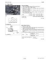
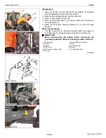
(10) Pressure Switch
Pressure Switch
1) HI Pressure Side
1. Connect the manifold gauge (3) to compressor as following
procedure.
Close the
HI
and
LO
pressure valves (4), (5) of manifold gauge
tightly, and connect the charging hoses (2), (1) (red and blue) to
the respective compressor service valves. (Refer to “[1]
HANDLING OF SERVICE TOOLS” in this section)
NOTE
Q
• Be sure to drive out the air in the charging hoses at the
manifold gauge connection end by utilizing the refrigerant
pressure in the refrigerant cycle.
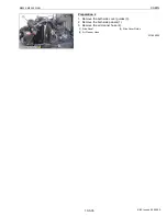
2. Start the engine and set at approx. 1500 min
−
1
(rpm). Turn on
the A/C switch, then set the blower switch to
HI
position.
3. Raise pressure on the
HI
pressure side of the refrigerant cycle by
covering the condenser front with a corrugated carboard, and the
pressure switch is activated and the compressor magnetic clutch
is turned off. At this time, read the
HI
pressure gauge of the
manifold gauge. If this pressure reading differs largely with the
setting pressure, replace the pressure switch with a new one.
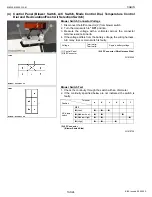
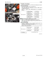
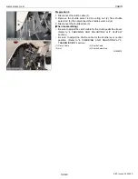
2) LO Pressure Side
1. Disconnect
2P
connector (6) of pressure switch.
2. Measure the resistance with an ohmmeter across the connector
terminals.
3. If 0 ohm is not indicated at normal condition, there is no
refrigerant in the refrigerating cycle because gas leaks or
pressure switch is defective.
(Reference)
• The resistance of pressure switch is 0 ohm in normal condition,
but it becomes infinity if the pressure is out of factory spec..
Because the pressure switch starts to work.
W1020509
Setting pressure
Factory
spec.
Pressure
switch
OFF
More than
approx. 3.14 MPa
32 kgf/cm
2
455 psi
Setting pressure
Factory
spec.
Pressure
switch
OFF
Less than
approx. 0.196 MPa
2.0 kgf/cm
2
28.4 psi
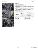
(1) Charging Hose (Blue)
(2) Charging Hose (Red)
(3) Manifold Gauge
(4)
HI
(High Pressure Side) Charging
Valve
(5)
LO
(Low Pressure Side) Charging
Valve
(6)
2P
Connector
KiSC issued 09, 2008 A
Summary of Contents for M9540
Page 1: ...M8540 M9540 WORKSHOP MANUAL TRACTOR KiSC issued 09 2008 A...
Page 8: ...6 M8540 M9540 WSM SAFETY INSTRUCTIONS KiSC issued 09 2008 A...
Page 9: ...7 M8540 M9540 WSM SAFETY INSTRUCTIONS KiSC issued 09 2008 A...
Page 10: ...8 M8540 M9540 WSM SAFETY INSTRUCTIONS Q CABIN Model KiSC issued 09 2008 A...
Page 11: ...9 M8540 M9540 WSM SAFETY INSTRUCTIONS KiSC issued 09 2008 A...
Page 12: ...10 M8540 M9540 WSM SAFETY INSTRUCTIONS KiSC issued 09 2008 A...
Page 16: ...14 M8540 M9540 WSM DIMENSIONS DIMENSIONS ROPS Model KiSC issued 09 2008 A...
Page 17: ...15 M8540 M9540 WSM DIMENSIONS CABIN Model KiSC issued 09 2008 A...
Page 18: ...G GENERAL KiSC issued 09 2008 A...
Page 103: ...1 ENGINE KiSC issued 09 2008 A...
Page 203: ...2 CLUTCH KiSC issued 09 2008 A...
Page 219: ...3 TRANSMISSION KiSC issued 09 2008 A...
Page 322: ...4 REAR AXLE KiSC issued 09 2008 A...
Page 323: ...CONTENTS MECHANISM 1 FEATURES 4 M1 KiSC issued 09 2008 A...
Page 336: ...5 BRAKES KiSC issued 09 2008 A...
Page 374: ...6 FRONT AXLE KiSC issued 09 2008 A...
Page 401: ...7 STEERING KiSC issued 09 2008 A...
Page 402: ...CONTENTS MECHANISM 1 STEERING MECHANISM 7 M1 2 STEERING CYLINDER 7 M2 KiSC issued 09 2008 A...
Page 420: ...8 HYDRAULIC SYSTEM KiSC issued 09 2008 A...
Page 473: ...9 ELECTRICAL SYSTEM KiSC issued 09 2008 A...
Page 554: ...10 CABIN KiSC issued 09 2008 A...