1-S59
M8540, M9540, WSM
ENGINE
Connecting Rod Cap
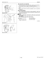
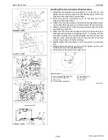
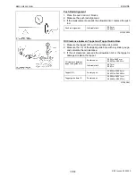
1. Remove the connecting rod screws (1) from connecting rod cap.
2. Remove the connecting rod caps.
(When reassembling)
• Align the marks
(a)
with each other. (Face the marks toward the
injection pump.)
• Apply engine oil to the connecting rod screws and lightly screw it
in by hand, then tighten it to the specified torque.
If the connecting rod screw won’t be screwed in smoothly, clean
the threads.
If the connecting rod screw is still hard to screw in, replace it.
• When using the existing crank pin metal again, put tally marks on
the crank pin metal and the connecting rod in order to keep their
positioning.
• Fit the crank pin metal in place : its centrally groove side toward
the connecting rod, and the non-grooved side toward the cap.
W1058252
Piston
1. Completely clean carbon in the cylinders.
2. Turn the flywheel and set a piston to the top dead center.
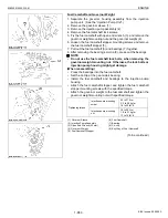
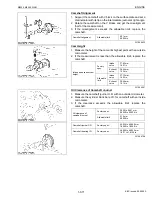
3. Pull out the piston upward by lightly tapping it from the bottom of
the crankcase with the grip of a hammer.
(When reassembling)
• Before inserting the piston into the cylinder, apply enough engine
oil to the cylinder.
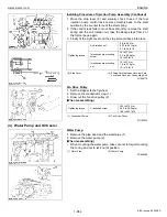
• When inserting the piston into the cylinder, face the mark (3) on
the connecting rod to the injection pump.
IMPORTANT
Q
• Do not change the combination of cylinder and piston.
Make sure of the position of each piston by marking. For
example, mark “1” on the No. 1 position.
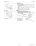
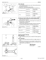
• When inserting the piston into the cylinder, place the gap of
each piston ring like the figure.
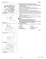
• Carefully insert the pistons using a piston ring compressor
(1). Otherwise, their chrome-plated section of piston rings
may be scratched, causing trouble inside the liner.
• When inserting the piston in place, be careful not to get the
molybdenum disulfide coating torn off its skirt. This coating
is useful in minimizing the clearance with the cylinder liner.
Just after the piston pin has been press-fitted, in particular,
the piston is still hot and the coating is easy to peel off. Wait
until the piston cools down.
W1058433
Tightening torque
Connecting rod screw
79 to 83 N·m
8.0 to 8.5 kgf·m
58 to 61 lbf·ft
(1) Connecting Rod Screw
(a) Mark
(1) Piston Ring Compressor
(2) Molybdenum Disulfide Coating in
piston skirt
(3) Mark
(a) 0.79 rad (45
°
)
(A) Top Ring Gap
(B) Second Ring Gap
(C) Oil Ring Gap
(D) Piston Pin Hole
(E) Injection Pump Side
KiSC issued 09, 2008 A
Summary of Contents for M9540
Page 1: ...M8540 M9540 WORKSHOP MANUAL TRACTOR KiSC issued 09 2008 A...
Page 8: ...6 M8540 M9540 WSM SAFETY INSTRUCTIONS KiSC issued 09 2008 A...
Page 9: ...7 M8540 M9540 WSM SAFETY INSTRUCTIONS KiSC issued 09 2008 A...
Page 10: ...8 M8540 M9540 WSM SAFETY INSTRUCTIONS Q CABIN Model KiSC issued 09 2008 A...
Page 11: ...9 M8540 M9540 WSM SAFETY INSTRUCTIONS KiSC issued 09 2008 A...
Page 12: ...10 M8540 M9540 WSM SAFETY INSTRUCTIONS KiSC issued 09 2008 A...
Page 16: ...14 M8540 M9540 WSM DIMENSIONS DIMENSIONS ROPS Model KiSC issued 09 2008 A...
Page 17: ...15 M8540 M9540 WSM DIMENSIONS CABIN Model KiSC issued 09 2008 A...
Page 18: ...G GENERAL KiSC issued 09 2008 A...
Page 103: ...1 ENGINE KiSC issued 09 2008 A...
Page 203: ...2 CLUTCH KiSC issued 09 2008 A...
Page 219: ...3 TRANSMISSION KiSC issued 09 2008 A...
Page 322: ...4 REAR AXLE KiSC issued 09 2008 A...
Page 323: ...CONTENTS MECHANISM 1 FEATURES 4 M1 KiSC issued 09 2008 A...
Page 336: ...5 BRAKES KiSC issued 09 2008 A...
Page 374: ...6 FRONT AXLE KiSC issued 09 2008 A...
Page 401: ...7 STEERING KiSC issued 09 2008 A...
Page 402: ...CONTENTS MECHANISM 1 STEERING MECHANISM 7 M1 2 STEERING CYLINDER 7 M2 KiSC issued 09 2008 A...
Page 420: ...8 HYDRAULIC SYSTEM KiSC issued 09 2008 A...
Page 473: ...9 ELECTRICAL SYSTEM KiSC issued 09 2008 A...
Page 554: ...10 CABIN KiSC issued 09 2008 A...


