


9-S17
M8540, M9540, WSM
ELECTRICAL SYSTEM
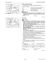
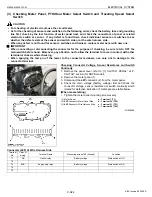
Magnet Switch Test
1. Disconnect the battery negative cable from the battery.
2. Disconnect the battery positive cable and the leads from the
starter terminal
B
(4).
3. Remove the starter from the engine.
4. Disconnect the connecting lead (3) from the starter terminal
C
(2).
5. Connect a jumper lead from the starter terminal
S
(1) to the
battery positive terminal post.
6. Connect a jumper lead momentarily between the starter terminal
C
(2) and the battery negative terminal post.
7. If the pinion gear does not pop out, check the magnetic switch.
NOTE
Q
• This test should be carried out for a short time, about 3 to 5
seconds.
(When reassembling)
W1023186
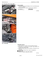
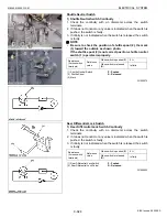
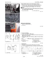
[5] ENGINE STOP SOLENOID
Functional Check
1. Remove the engine stop solenoid (2) from the injection pump.
2. Connect the leads as shown in the figure.
- Connect the jumper leads from terminal
P
through the switch
(4) to the battery positive terminal
- Connect the jumper leads from terminal
H
through the switch
(3) to the battery positive terminal
- Connect the jumper leads from the negative terminal to the
engine stop solenoid body
3. When switch (4) is turn
ON
, the plunger is pulled into the solenoid
body and then turn
OFF
the switch (4), the plunger comes out.
4. Turn on the switch (3) then turn
ON
the switch (4), the plunger is
pulled into the solenoid body and it is kept in
HOLDING
position
after turning
OFF
the switch (4).
5. If the plunger is not attracted, the engine stop solenoid is faulty.
IMPORTANT
Q
• Never apply the current for pulling coil more than two
seconds when inspecting.
W1024150
Tightening torque
Starter
B
terminal
9.8 to 11.8 N·m
1.0 to 1.2 kgf·m
7.2 to 8.7 lbf·ft
(1) Terminal
S
(2) Terminal
C
(3) Connecting Lead
(4) Terminal
B
(1) Connector
(2) Engine Stop Solenoid
(3) Switch for Holding Coil
(4) Switch for Pulling Coil
(5) Battery
P : Terminal for Pulling Coil
H : Terminal for Holding Coil
KiSC issued 09, 2008 A
Summary of Contents for M9540
Page 1: ...M8540 M9540 WORKSHOP MANUAL TRACTOR KiSC issued 09 2008 A...
Page 8: ...6 M8540 M9540 WSM SAFETY INSTRUCTIONS KiSC issued 09 2008 A...
Page 9: ...7 M8540 M9540 WSM SAFETY INSTRUCTIONS KiSC issued 09 2008 A...
Page 10: ...8 M8540 M9540 WSM SAFETY INSTRUCTIONS Q CABIN Model KiSC issued 09 2008 A...
Page 11: ...9 M8540 M9540 WSM SAFETY INSTRUCTIONS KiSC issued 09 2008 A...
Page 12: ...10 M8540 M9540 WSM SAFETY INSTRUCTIONS KiSC issued 09 2008 A...
Page 16: ...14 M8540 M9540 WSM DIMENSIONS DIMENSIONS ROPS Model KiSC issued 09 2008 A...
Page 17: ...15 M8540 M9540 WSM DIMENSIONS CABIN Model KiSC issued 09 2008 A...
Page 18: ...G GENERAL KiSC issued 09 2008 A...
Page 103: ...1 ENGINE KiSC issued 09 2008 A...
Page 203: ...2 CLUTCH KiSC issued 09 2008 A...
Page 219: ...3 TRANSMISSION KiSC issued 09 2008 A...
Page 322: ...4 REAR AXLE KiSC issued 09 2008 A...
Page 323: ...CONTENTS MECHANISM 1 FEATURES 4 M1 KiSC issued 09 2008 A...
Page 336: ...5 BRAKES KiSC issued 09 2008 A...
Page 374: ...6 FRONT AXLE KiSC issued 09 2008 A...
Page 401: ...7 STEERING KiSC issued 09 2008 A...
Page 402: ...CONTENTS MECHANISM 1 STEERING MECHANISM 7 M1 2 STEERING CYLINDER 7 M2 KiSC issued 09 2008 A...
Page 420: ...8 HYDRAULIC SYSTEM KiSC issued 09 2008 A...
Page 473: ...9 ELECTRICAL SYSTEM KiSC issued 09 2008 A...
Page 554: ...10 CABIN KiSC issued 09 2008 A...