


Goodrive300
inverters Appendix D
296
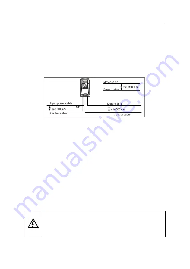
power cable and control cables are installed on separate trays. Avoid long parallel runs of
motor cables with other cables to decrease electromagnetic interference caused by the rapid
changes in the drive output voltage.
Where control cables must cross power cables make sure that they are arranged at an angle
as near to 90 degrees as possible.
The cable trays must have good electrical bonding to each other and to the grounding
electrodes. Aluminum tray systems can be used to improve local equalizing of potential.
A figure of the cable routing is shown below.
D.4.4 Insulation checking
Check the insulation of the motor and motor cable as follows:
1. Check that the motor cable is connected to the motor and disconnected from the drive
output terminals U, V and W.
2. Measure the insulation resistance between each phase conductor and the Protective
Earth conductor using a measuring voltage of 500 V DC.
For the insulation resistance of
other motors, please consult the manufacturer’s instructions.
Note: Moisture inside the motor casing will reduce the insulation resistance. If moisture is
suspected, dry the motor and repeat the measurement.
D.5 Breaker and electromagnetic contactor
It is necessary to add fuse for the avoidance of overload.
It is appropriate to use a breaker (MCCB) which complies with the inverter power in the
3-phase AC power and input power and terminals (R,S,T). The capacity of the inverter
should be 1.5-2 times of the rated current.
Due to the inherent operating principle and construction of circuit breakers,
independent of the manufacturer, hot ionized gases may escape from the
breaker enclosure in case of a short-circuit. To ensure safe use, special
attention must be paid to the installation and placement of the breakers.
Summary of Contents for GD300-004G-4
Page 1: ...3...
Page 148: ...Goodrive300 inverters Basic operation instruction 147...
Page 159: ...Goodrive300 inverters Basic operation instruction 158...
Page 164: ...Goodrive300 inverters Basic operation instruction 163...
Page 173: ...Goodrive300 inverters Basic operation instruction 172...
Page 189: ...Goodrive300 inverters Basic operation instruction 188...
Page 204: ...Goodrive300 inverters Basic operation instruction 203...
Page 227: ...Goodrive300 inverters Fault tracking 226 8 6 2 Motor vibration...
Page 228: ...Goodrive300 inverters Fault tracking 227 8 6 3 Overvoltage 8 6 4 Undervoltage fault...
Page 312: ...1 1 0 0 1 0 0 7 7 9 C E 66001 00035 201303 V1 4...


