


Goodrive300
inverters Function codes
122
Functi
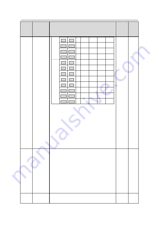
on
code
Name
Detailed instruction of parameters
Default
value
Modif
y
BIT9
BIT8
4
00
01
10
11
BIT11 BIT10
5
00
01
10
11
BIT13 BIT12
6
00
01
10
11
BIT15 BIT14
7
00
01
10
11
BIT1
BIT0
8
00
01
10
11
BIT3
BIT2
9
00
01
10
11
BIT5
BIT4
10
00
01
10
11
BIT7
BIT6
11
00
01
10
11
BIT9
BIT8
12
00
01
10
11
BIT11 BIT10 13
00
01
10
11
BIT13 BIT12 14
00
01
10
11
P10.35
BIT15 BIT14 15
00
01
10
11
After users select the corresponding ACC/DEC
time, the combining 16 binary bit can be changed
into hexadecimal bit, and then set the
corresponding function codes.
ACC/DEC time 1 is aet by P00.11 and P00.12;
ACC/DEC time 2 is aet by P08.00 and P08.01;
ACC/DEC time 3 is aet by P08.02 and P08.03;
ACC/DEC time 4 is aet by P08.04 and P08.05.
Setting range: -0x0000~0xFFFF
P10.36 PLC restart
0: Restart from the first step; stop during running
(cause by the stop command, fault or power loss),
run from the first stage after restart.
1: Continue to run from the stop frequency; stop
during running(cause by stop command and fault),
the inverter will record the running time
automatically, enter into the stage after restart and
keep the remaining running at the setting
frequency.
0
◎
P10.37
Multi-step
time unit
0: Seconds
;
the running time of all steps is counted
by second
0
◎
Summary of Contents for GD300-004G-4
Page 1: ...3...
Page 148: ...Goodrive300 inverters Basic operation instruction 147...
Page 159: ...Goodrive300 inverters Basic operation instruction 158...
Page 164: ...Goodrive300 inverters Basic operation instruction 163...
Page 173: ...Goodrive300 inverters Basic operation instruction 172...
Page 189: ...Goodrive300 inverters Basic operation instruction 188...
Page 204: ...Goodrive300 inverters Basic operation instruction 203...
Page 227: ...Goodrive300 inverters Fault tracking 226 8 6 2 Motor vibration...
Page 228: ...Goodrive300 inverters Fault tracking 227 8 6 3 Overvoltage 8 6 4 Undervoltage fault...
Page 312: ...1 1 0 0 1 0 0 7 7 9 C E 66001 00035 201303 V1 4...


