8
IBM
Eserver
xSeries 455 Planning and Installation Guide
Memory controller
A single memory controller, code named “Cyclone”, located within the
memory-board assembly.
Two PCI-X bridges
Two PCI-X bridges, code named “Winnipeg”, one located on the PCI-X board
and the other on the I/O board. These control both the PCI-X and Remote I/O.
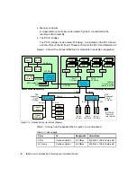
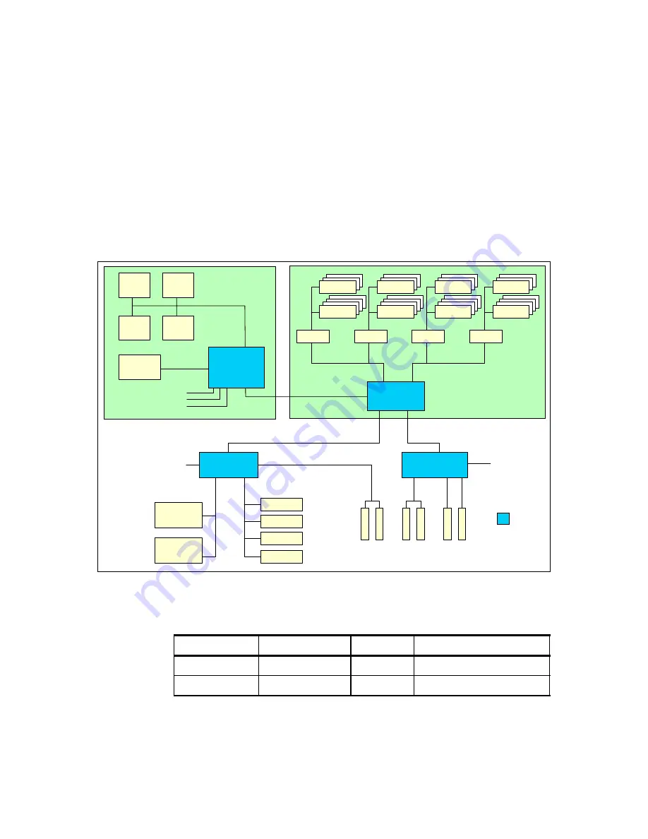
Figure 1-4 shows the various IBM XA-64 components in an x455 configuration.
Figure 1-4 xSeries 455 system block diagram
Table 1-3 shows how the bandwidths in Figure 1-4 are calculated.
Table 1-3 Bus speeds
Ultra320
SCSI
Gigabit
Ethernet
Video
3x USB
Serial
RSA
33 MHz
66 MHz
64-bit
66 MHz
64-bit
100 MHz
64-bit
133 MHz
Bus A
66 MHz
RXE
Expansion
Port A
(1 GBps)
B-100
D-133
C-133
IBM XA-64
("Summit")
core chipset
6.4 GBps
64 MB
L4 cache
400 MHz
3.2 GBps
CPU 1
CPU 2
CPU 3
CPU 4
PCI-X bridge
PCI-X bridge
RXE
Expansion
Port B
(1 GBps)
1 GBps
1 GBps
200 MHz
2-way or 4-way
interleaved DDR
Port 2
3.2 GBps
Port 1
3.2 GBps
DDR
DDR
DDR
DDR
DDR
DDR
SMI-E
DDR
DDR
Memory
controller
SMI-E
SMI-E
SMI-E
6.4 GBps
Processor-board assembly
Memory-board assembly
Cache and
scalability
controller
SMP scalability
ports
From
To
Bandwidth
Calculation
CPUs
Cache controller
6.4 GBps
400 MHz x 128-bit data path
L4 Cache
Cache controller
6.4 GBps
400 MHz x 128-bit data path
Summary of Contents for 88553RX
Page 2: ......
Page 214: ...200 IBM Eserver xSeries 455 Planning and Installation Guide Figure 5 14 Connect to the x455...
Page 228: ...214 IBM Eserver xSeries 455 Planning and Installation Guide...
Page 229: ...IBM Eserver xSeries 455 Planning and Installation Guide...
Page 230: ......
Page 231: ......


