


www.geehy.com Page 229
The following table shows the priority sequence followed by the output
mechanism:
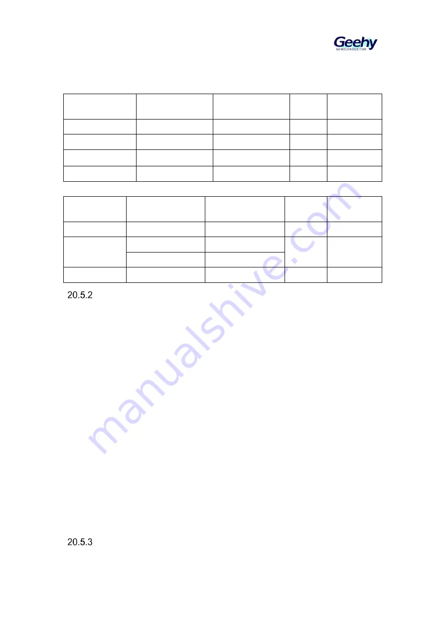
Table 61 PC14 Pin Controlled by LSECLK
Pin configuration
and function
RCM_RTCCTRL
LSEEN bit of register
RCM_RTCCTRL
LSEBCFG bit of
register
PC14EN
PC14VAL
LSECLK oscilltor
1
0
No effect
No effect
LSECLK bypass
1
1
No effect
No effect
Forced to push-pull
output
0
No effect
1
PC14 output
data value
Standard GPIO
0
No effect
0
No effect
Table 62 PC15 Pin Controlled by LSECLK
Pin
configuration
and function
RCM_RTCCTRL
LSEEN bit of register
RCM_RTCCTRL
LSEBCFG bit of
register
PC15EN
PC15VAL
LSECLK oscilltor
1
0
No effect
No effect
Forced to
push-pull output
1
1
1
PC15 output
data value
0
No effect
Standard GPIO
0
No effect
0
No effect
Timebase Unit
Clock source
RTC has three clock sources RTC_CLK:
External LSECLK crystal oscillator
External HSECLK crystal oscillator
Internal LSICLK
Different clock sources are configured through RCM peripheral of clock
controller.
Prescaler
The power consumption of RTC peripheral should be minimized as far as
possible. In order to give consideration to the power consumption, dual
prescalers, 7bit asynchronous prescaler APSC and 15bit synchronous prescaler
SPSC are used in RTC.
RTC_CLK first passes through the asynchronous prescaler, and the clock after
frequency division reaches the synchronous prescaler. Two prescalers can be
reasonably configured to generate a 1Hz clock for calendar.
When the prescaler is used, it is suggested that the asynchronous prescaler
should be adjusted as high as possible to reduce power consumption.
The synchronous prescaled value can also be used as the reload value of the
subsecond counter.
Clock Calibration
Clock synchronization


