xr
PRELIMINARY
XRT86VL38
REV. P1.0.6
OCTAL T1/E1/J1 FRAMER/LIU COMBO
128
T
ABLE
43: I
NTERRUPT
C
ONTROL
R
EGISTER
R
EGISTER
26 I
NTERRUPT
C
ONTROL
R
EGISTER
(ICR) H
EX
A
DDRESS
: 0
X
n11A
B
IT
F
UNCTION
T
YPE
D
EFAULT
D
ESCRIPTION
-O
PERATION
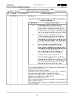
7-3
Reserved
-
-
Reserved
2
INT_WC_RUR
R/W
0
Interrupt Write-to-Clear or Reset-upon-Read Select
This READ/WRITE bit-field configures all Interrupt Status bits to be
either Reset Upon Read or Write-to-Clear
0=Setting this bit to ‘0’ will configure all Interrupt Status bits to be
Reset Upon Read (RUR).
1=Setting this bit to ‘1’ will configure all Interrupt Status bits to be
Write-to-Clear (WC).
1
ENBCLR
R/W
0
Interrupt Enable Auto Clear
This READ/WRITE bit-field configures all interrupt enable bits to
clear or not clear after reading the interrupt status bit.
0= Setting this bit to ‘0’ will configure all Interrupt Enable bits to not
cleared after reading the interrupt status bit. The corresponding
Interrupt Enable bit will stay ‘high’ after reading the interrupt status
bit.
1= Setting this bit to ‘1’ will configure all interrupt Enable bits to clear
after reading the interrupt status bit. The corresponding interrupt
enable bit will be set to ‘low’ after reading the interrupt status bit.
0
INTRUP_ENB
R/W
0
Interrupt Enable for Framer_n
This READ/WRITE bit-field enables the T1/E1 Framer for Interrupt
Generation.
0 = Setting this bit to ‘0’ disables the T1/E1 framer block for Interrupt
Generation
1 = Setting this bit to ‘1’ enables the T1/E1 framer block for Interrupt
Generation
T
ABLE
44: LAPD S
ELECT
R
EGISTER
R
EGISTER
27 LAPD S
ELECT
R
EGISTER
(LAPDSR) H
EX
A
DDRESS
: 0
X
n11B
B
IT
F
UNCTION
T
YPE
D
EFAULT
D
ESCRIPTION
-O
PERATION
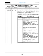
[7:2] Reserved
-
-
Reserved
[1:0] LAPDsel
R/W
0
LAPD Select
These two READ/WRITE bit-fields select one of the LAPD channel
being used. These bits will determine which HDLC controller has
access to the Read/Write registers 0xn600 and 0xn700 for storing or
extracting LAPD messages.
00 = Setting these two bits to ‘00’ will select HDLC Controller 1
01 = Setting these two bits to ‘01’ will select HDLC Controller 2
10 = Setting these two bits to ‘10’ will select HDLC Controller 3
11 = Setting these two bits to ‘11’ will select HDLC Controller 1


