


XRT86VL38
PRELIMINARY
xr
OCTAL T1/E1/J1 FRAMER/LIU COMBO
REV. P1.0.6
127
T
ABLE
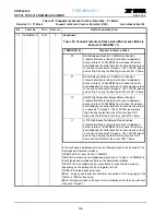
42: DMA 1 (R
EAD
) C
ONFIGURATION
R
EGISTER
R
EGISTER
25 DMA 1 (R
EAD
) C
ONFIGURATION
R
EGISTER
(D1CR) H
EX
A
DDRESS
: 0
X
n119
B
IT
F
UNCTION
T
YPE
D
EFAULT
D
ESCRIPTION
-O
PERATION
7-6
Reserved
-
-
Reserved
7
DMA1 RST
R/W
0
DMA_1 Reset
This READ/WRITE bit-field resets the Receive DMA (Read) Channel 1
0 = Normal operation.
1 = A zero to one transition resets the Receive DMA (Read) channel 1.
6
DMA1 ENB
R/W
0
DMA1_ENB
This READ/WRITE bit-field enables the Receive DMA_1 (Read) inter-
face. After a receive DMA is enabled, DMA transfers are only
requested when the receive cell buffer contains a complete message
or cell.
The DMA read channel is used by the T1/E1 Framer to transfer data
from the HDLC buffers within the T1/E1 Framer to external memory.
The DMA Read cycle starts by T1/E1 Framer asserting the DMA
Request (REQ1) ‘low’, then the external DMA controller should drive
the DMA Acknowledge (ACK1) ‘low’ to indicate that it is ready to
receive the data. The T1/E1 Framer should place new data on the
Microprocessor data bus each time the Read Signal is Strobed low if
the RD is configured as a Read Strobe. If RD is configured as a direc-
tion signal, then the T1/E1 Framer would place new data on the Micro-
processor data bus each time the Write Signal (WR) is Strobed low.
0 = Setting this bit to ‘0’ disables the DMA_1 (Read) interface
1 = Setting this bit to ‘1’ enables the DMA_1 (Read) interface
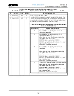
5
RD TYPE
R/W
0
READ Type Select
This READ/WRITE bit-field selects the function of the RD signal.
0 = When this bit is set to ‘0’, RD functions as a Read Strobe signal
1 = When this bit is set to ‘1’, RD acts as a direction signal (indicates
whether the current bus cycle is a read or write operation), and WR
works as a data strobe.
4 - 3 Reserved
-
-
Reserved
2
DMA1_CHAN(2)
R/W
0
Channel Select
These three READ/WRITE bit-fields select which T/E1 channel within
the chip uses the Receive DMA_1 (Read) interface.
000 = Channel 0
001 = Channel 1
001 = Channel 2
011 = Channel 3
100 = Channel 4
101 = Channel 5
110 = Channel 6
111 = Channel 7
1
DMA1_CHAN(1)
R/W
0
0
DMA1_CHAN(0)
R/W
0


