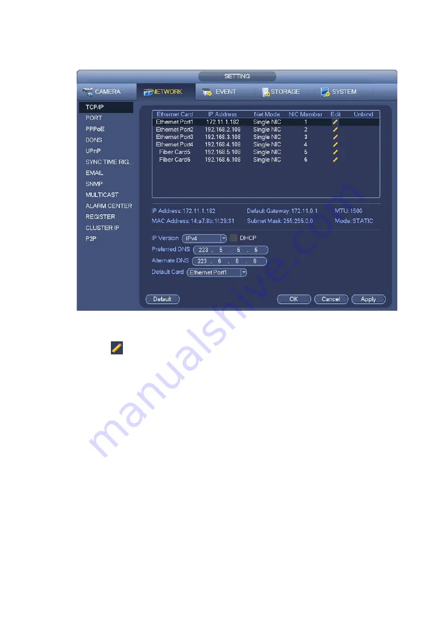
For the IP address of IPv6 version, default gateway, preferred DNS and alternate DNS, the input
value shall be 128-digit. It shall not be left in blank.
Figure 3-172
Click Edit button
, you can go to the following interface. See Figure 3-173.
Network mode:
Single NIC: eth1/eth2/ eth3/eth4 operate separately. You can use the services such as HTTP,
RTP service via eth1/eth2/ eth3/eth4. Usually you need to set one default card (default setup is
eth1) to request the auto network service from the device-end such as DHCP, email, FTP and
etc. In multiple-address mode, system network status is shown as offline once one card is
offline.
Network fault-tolerance: In this mode, device uses bond0 to communicate with the external
devices. You can focus on one host IP address. At the same time, you need to set one master
card. Usually there is only one running card (master card).System can enable alternate card
when the master card is malfunction. The system is shown as offline once these two cards are
both offline.
Load balance: In this mode, device uses bond0 to communicate with the external device. The
eth1/eth2/ eth3/eth4 are working now and bearing the network load. Their network load are
general the same. The system is shown as offline once all cards are offline.
Note:
Different series products have different Ethernet port amount.
NIC member: You can check the box here to select the bind cards.
This mode is for fault-tolerance or load balance mode only.
The network cards number shall be equal to or more than 2.
The different types of cards such as fiber card or the Ethernet card can not binding together.
Содержание ELITE Network IP Series
Страница 1: ...64 Channel 4K Hot Swap NVR NVR ELHS 64 4K DH...
Страница 43: ...Figure 3 14 Step 2 Click Add new holiday button and device displays the following interface See Figure 3 15...
Страница 108: ...Figure 3 92 Figure 3 93...
Страница 131: ...Figure 3 111 Figure 3 112 Figure 3 113...
Страница 144: ...Figure 3 126 Figure 3 127...
Страница 146: ...Figure 3 129 Click draw button to draw the zone See Figure 3 130 Figure 3 130...
Страница 149: ...Figure 3 133 Click Draw button to draw a zone See Figure 3 134 Figure 3 134...
Страница 154: ...Figure 3 139 Click draw button to draw the zone See Figure 3 140...
Страница 165: ...Figure 3 151 Step 2 Add surveillance scene 1 Click Add The Add interface is displayed See Figure 3 152...
Страница 172: ...Figure 3 157 Figure 3 158...
Страница 173: ...Figure 3 159 Figure 3 160...
Страница 176: ...Figure 3 164 Figure 3 165...
Страница 211: ...Figure 3 199...
Страница 218: ...Figure 3 206 Step 2 Click Add user button in Figure 3 206 The interface is shown as in Figure 3 207 Figure 3 207...
Страница 234: ...Figure 3 227 Step 2 Click Add group Enter add group interface See Figure 3 228 Figure 3 228...
Страница 298: ...Figure 4 56 Figure 4 57...
Страница 304: ...Figure 4 62 Figure 4 63...
Страница 305: ...Figure 4 64 Figure 4 65...
Страница 330: ...Figure 4 101 Figure 4 102...
Страница 339: ...Figure 4 115 Figure 4 116...
Страница 359: ...Figure 4 144 Note For admin you can change the email information See Figure 4 145...


