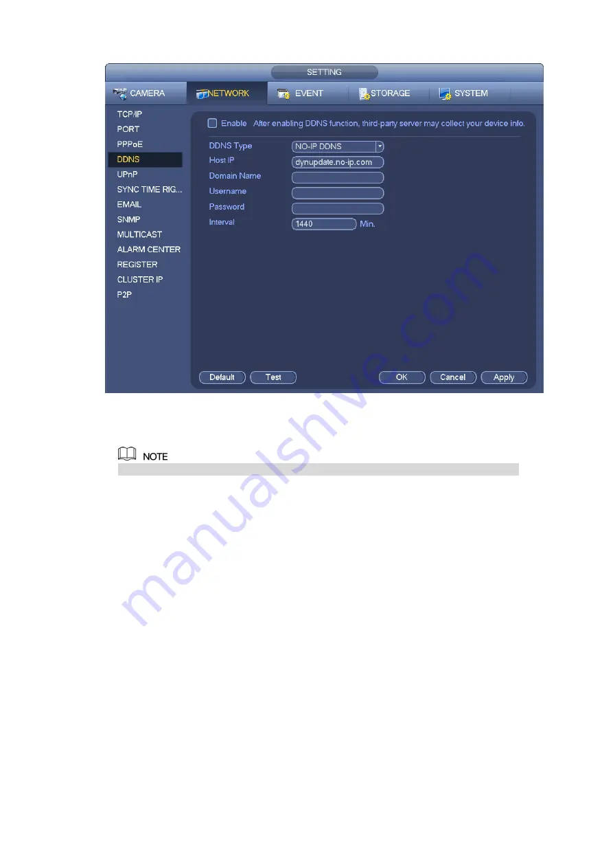
Figure 3-176
Step 2 Select the Enable check box to enable DDNS function.
When DDNS is enabled, the third-party server might collect your device information.
Step 3 Configure the DDNS parameters according to practical situation.
Type/address:
Dyndns DDNS is members.dyndns.org.
NO-IP DDNS is dynupdate.no-ip.com.
CN99 DDNS is members.3322.org.
Domain: The domain name registered on the DDNS service provider website.
User name/password: Input the user name and password got from the DDNS service provider. Make
sure you have logged in the DDNS service provider website to register an account (user name and
password).
Interval: After DDNS boots up, it sends out refresh query regularly. The unit is minute.
Step 4 Click Apply or Save to complete setup.
Step 5 Open a browser and input domain name, click Enter key.
The setting is right if you can view device WEB interface. Otherwise, please check the parameters.
3.11.1.5 UPnP
The UPNP protocol is to establish a mapping relationship between the LAN and the WAN. Please input
the router IP address in the LAN in Figure 3-172. See Figure 3-177.
UPNP on/off
:
Turn on or off the UPNP function of the device.
Status: When the UPNP is offline, it shows as “Unknown”. When the UPNP works it shows
“Success”
Содержание ELITE Network IP Series
Страница 1: ...64 Channel 4K Hot Swap NVR NVR ELHS 64 4K DH...
Страница 43: ...Figure 3 14 Step 2 Click Add new holiday button and device displays the following interface See Figure 3 15...
Страница 108: ...Figure 3 92 Figure 3 93...
Страница 131: ...Figure 3 111 Figure 3 112 Figure 3 113...
Страница 144: ...Figure 3 126 Figure 3 127...
Страница 146: ...Figure 3 129 Click draw button to draw the zone See Figure 3 130 Figure 3 130...
Страница 149: ...Figure 3 133 Click Draw button to draw a zone See Figure 3 134 Figure 3 134...
Страница 154: ...Figure 3 139 Click draw button to draw the zone See Figure 3 140...
Страница 165: ...Figure 3 151 Step 2 Add surveillance scene 1 Click Add The Add interface is displayed See Figure 3 152...
Страница 172: ...Figure 3 157 Figure 3 158...
Страница 173: ...Figure 3 159 Figure 3 160...
Страница 176: ...Figure 3 164 Figure 3 165...
Страница 211: ...Figure 3 199...
Страница 218: ...Figure 3 206 Step 2 Click Add user button in Figure 3 206 The interface is shown as in Figure 3 207 Figure 3 207...
Страница 234: ...Figure 3 227 Step 2 Click Add group Enter add group interface See Figure 3 228 Figure 3 228...
Страница 298: ...Figure 4 56 Figure 4 57...
Страница 304: ...Figure 4 62 Figure 4 63...
Страница 305: ...Figure 4 64 Figure 4 65...
Страница 330: ...Figure 4 101 Figure 4 102...
Страница 339: ...Figure 4 115 Figure 4 116...
Страница 359: ...Figure 4 144 Note For admin you can change the email information See Figure 4 145...


