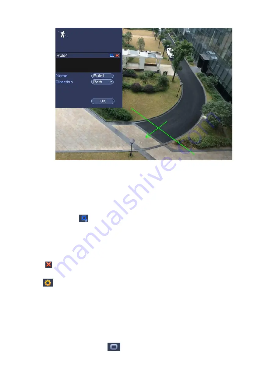
Figure 3-124
Select direction, and then input customized rule name.
Preset: Select a preset you want to use IVS.
Name: Input customized rule name.
Direction (A→B/B→A/A↔B): System can generate an alarm once there is any object crossing in the
specified direction.
Target filter: Click
, you can set filter object size. Each rule can set two sizes (min size/max size).
Once the object is smaller than the min size or larger than the max size, there is no alarm. Please
make sure the max size is larger than the min size.
Now you can draw a rule. Left click mouse to draw a tripwire. The tripwire can be a direct line, curve or
polygon. Right click mouse to complete.
Tips
Click
to delete the corresponding rule.
Click
, you can see the following interface. See Figure 3-125.
You can refer to the following information to set other parameters.
Channel: Select a channel from the dropdown list to set tripwire function.
Enable: Check the box here to enable tripwire function.
Rule: input customized rule name here.
Period: Click set button, you can see an interface is shown as in Figure 3-113. Here you can set
tripwire period. System only enables tripwire operation in the specified periods. There are two ways
for you to set periods. Please note system only supports 6 periods in one day.
In Figure 3-113, Select icon
of several dates, all checked items can be edited together.
Содержание ELITE Network IP Series
Страница 1: ...64 Channel 4K Hot Swap NVR NVR ELHS 64 4K DH...
Страница 43: ...Figure 3 14 Step 2 Click Add new holiday button and device displays the following interface See Figure 3 15...
Страница 108: ...Figure 3 92 Figure 3 93...
Страница 131: ...Figure 3 111 Figure 3 112 Figure 3 113...
Страница 144: ...Figure 3 126 Figure 3 127...
Страница 146: ...Figure 3 129 Click draw button to draw the zone See Figure 3 130 Figure 3 130...
Страница 149: ...Figure 3 133 Click Draw button to draw a zone See Figure 3 134 Figure 3 134...
Страница 154: ...Figure 3 139 Click draw button to draw the zone See Figure 3 140...
Страница 165: ...Figure 3 151 Step 2 Add surveillance scene 1 Click Add The Add interface is displayed See Figure 3 152...
Страница 172: ...Figure 3 157 Figure 3 158...
Страница 173: ...Figure 3 159 Figure 3 160...
Страница 176: ...Figure 3 164 Figure 3 165...
Страница 211: ...Figure 3 199...
Страница 218: ...Figure 3 206 Step 2 Click Add user button in Figure 3 206 The interface is shown as in Figure 3 207 Figure 3 207...
Страница 234: ...Figure 3 227 Step 2 Click Add group Enter add group interface See Figure 3 228 Figure 3 228...
Страница 298: ...Figure 4 56 Figure 4 57...
Страница 304: ...Figure 4 62 Figure 4 63...
Страница 305: ...Figure 4 64 Figure 4 65...
Страница 330: ...Figure 4 101 Figure 4 102...
Страница 339: ...Figure 4 115 Figure 4 116...
Страница 359: ...Figure 4 144 Note For admin you can change the email information See Figure 4 145...


