Parameter
Description
Noise
Video noise can be defined as the image quality degradation caused by
optical system distortion or hardware device during transmission.
Color Cast
Generally, video images are color images that contain color information,
such as RGB. When these three components in the image appear in some
unusual proportion, it means that the image has a color cast.
Out of Focus
The image with good definition contains rich details. The reason for the
image definition decline is that the generation of blurring phenomenon.
Image blurring is a common image quality reduction problem. In the process
of image acquisition, transmission and processing, many factors will cause
the image blurring, which is defined as out of focus in video diagnosis
Overexposure
The brightness of the image refers to the intensity of image pixels. Black is
the darkest while white is the brightest. Black is represented by 0 and white
is represented by 255. It indicates the brightness degree of the image. When
the brightness value of the whole image exceeds the threshold value, it is
defined as overexposure.
Step 5 Click OK to save the configuration.
System returns to Figure 4-73.
Step 6 Configure the alarm activation parameters.
Step 7 Click OK or Apply to save the configuration.
4.6.4.2 IVS Plan
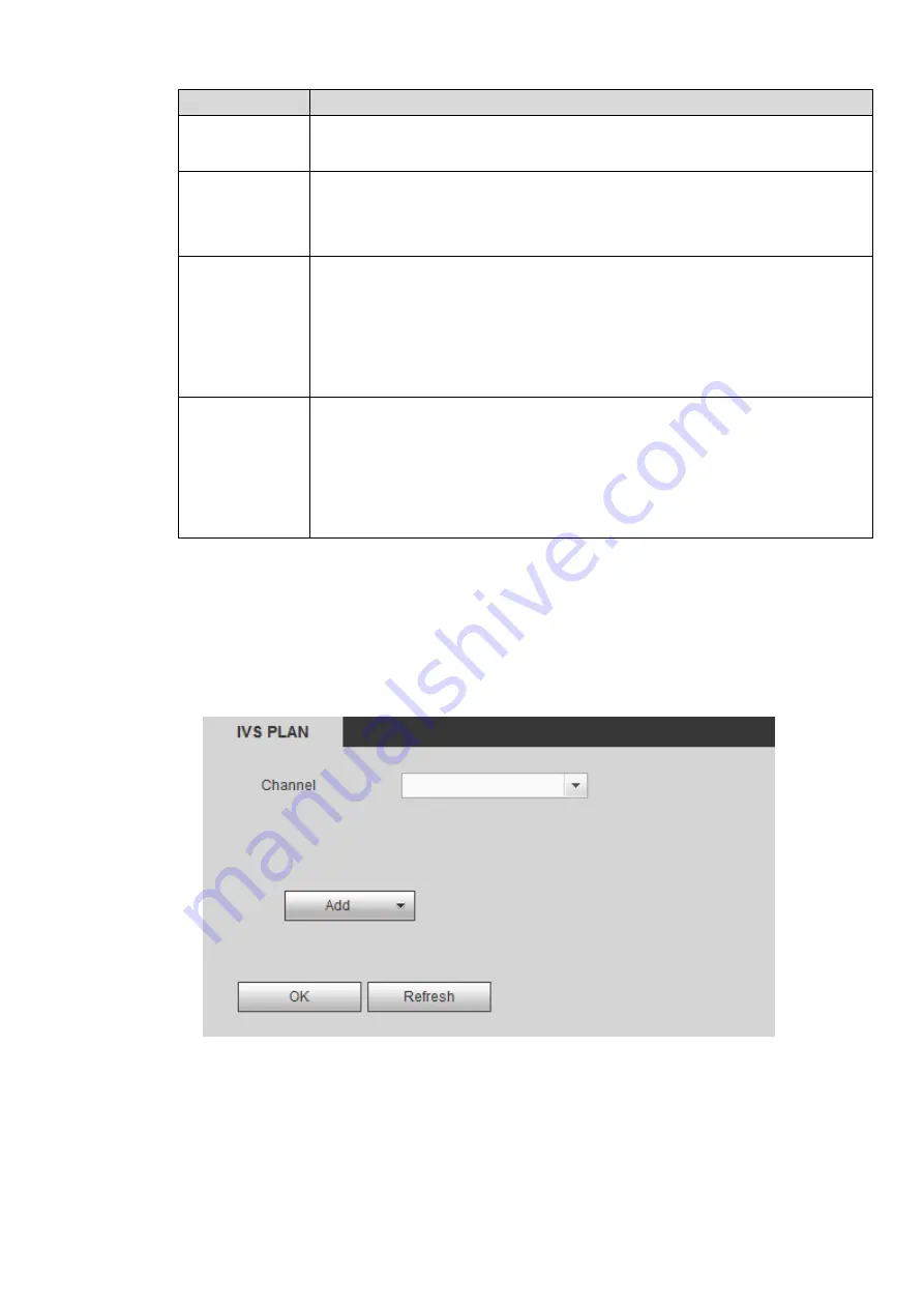
From main menu>Setup>Event>IVS plan, you can go to the IVS plan interface. See Figure 4-75.
Figure 4-75
Select a channel from the dropdown list. Click Add button, you can see an interface shown as below. See
Select a channel from the dropdown list and then set preset. Click Add button and then set the
corresponding rule.
Содержание ELITE Network IP Series
Страница 1: ...64 Channel 4K Hot Swap NVR NVR ELHS 64 4K DH...
Страница 43: ...Figure 3 14 Step 2 Click Add new holiday button and device displays the following interface See Figure 3 15...
Страница 108: ...Figure 3 92 Figure 3 93...
Страница 131: ...Figure 3 111 Figure 3 112 Figure 3 113...
Страница 144: ...Figure 3 126 Figure 3 127...
Страница 146: ...Figure 3 129 Click draw button to draw the zone See Figure 3 130 Figure 3 130...
Страница 149: ...Figure 3 133 Click Draw button to draw a zone See Figure 3 134 Figure 3 134...
Страница 154: ...Figure 3 139 Click draw button to draw the zone See Figure 3 140...
Страница 165: ...Figure 3 151 Step 2 Add surveillance scene 1 Click Add The Add interface is displayed See Figure 3 152...
Страница 172: ...Figure 3 157 Figure 3 158...
Страница 173: ...Figure 3 159 Figure 3 160...
Страница 176: ...Figure 3 164 Figure 3 165...
Страница 211: ...Figure 3 199...
Страница 218: ...Figure 3 206 Step 2 Click Add user button in Figure 3 206 The interface is shown as in Figure 3 207 Figure 3 207...
Страница 234: ...Figure 3 227 Step 2 Click Add group Enter add group interface See Figure 3 228 Figure 3 228...
Страница 298: ...Figure 4 56 Figure 4 57...
Страница 304: ...Figure 4 62 Figure 4 63...
Страница 305: ...Figure 4 64 Figure 4 65...
Страница 330: ...Figure 4 101 Figure 4 102...
Страница 339: ...Figure 4 115 Figure 4 116...
Страница 359: ...Figure 4 144 Note For admin you can change the email information See Figure 4 145...


