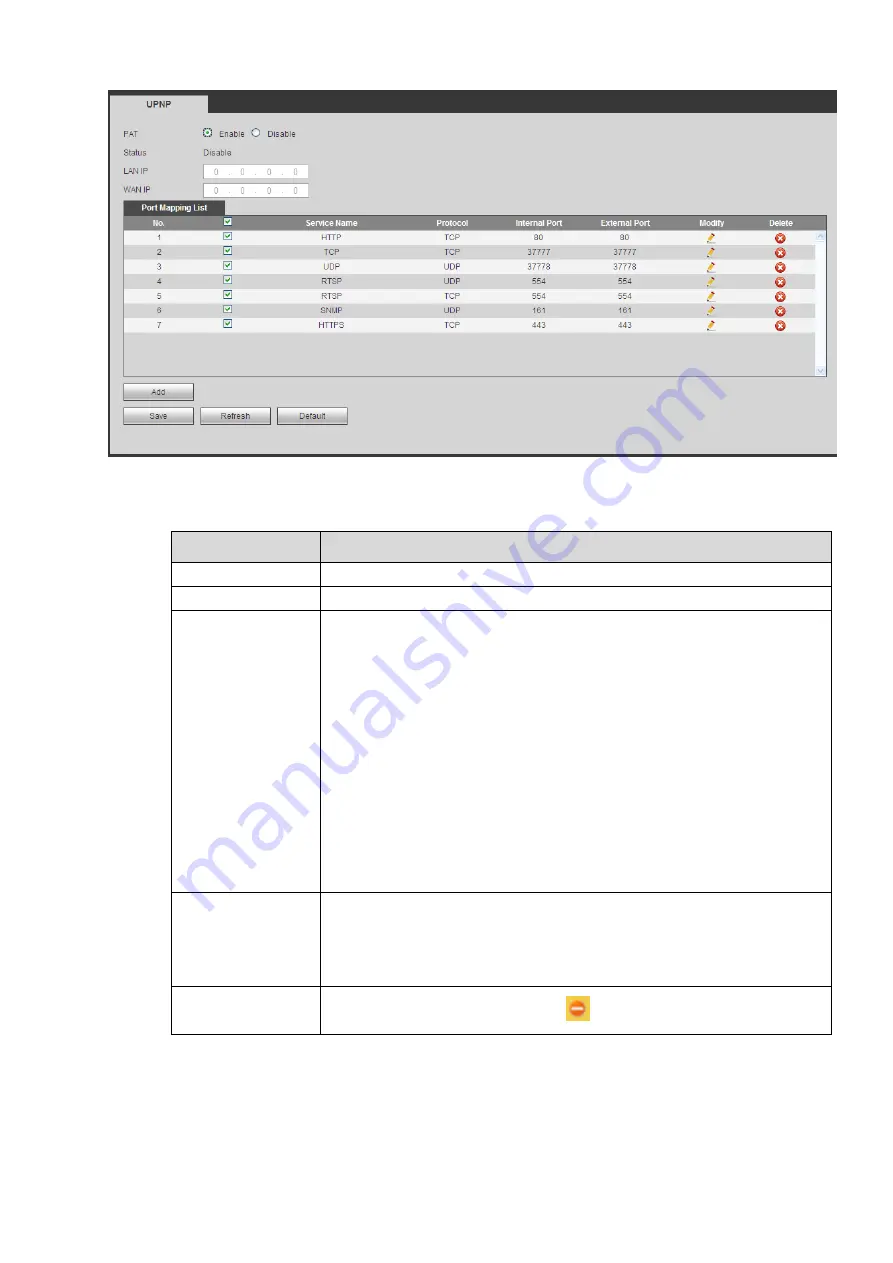
Figure 4-46
Please refer to the following sheet for detailed information.
Parameter
Function
PAT
Check the corresponding box to enable PAT function.
Status
Display UPnP function status.
Port mapping list
It is corresponding to the UPnP mapping information on the router.
Check the box before the service name to enable current PAT service.
Otherwise, the service is null.
Service name: Customized name.
Protocol: Protocol type.
Internal port: The port mapped to the port.
External port: The port current device needs to map.
Device has three mapping items: HTTP/TCP/UDP.
Note
When you set the external port (outport) of the router, the value ranges
from 1024 to 5000. Do not use port 1
~
255 or system port 256
~
1023,
in case there is conflict.
Add
Click Add button to add map relationship.
Note
For the data transmission protocol TCP/UDP, the external port and the
internal port shall be the same to guarantee proper data transmission.
Delete
Select one service and then click
to delete map relationship.
4.6.2.8 SNMP
The SNMP interface is shown as in Figure 4-47.
The SNMP allows the communication between the network management work station software and the
proxy of the managed device. It is reserved for the 3
rd
party to develop.
Содержание ELITE Network IP Series
Страница 1: ...64 Channel 4K Hot Swap NVR NVR ELHS 64 4K DH...
Страница 43: ...Figure 3 14 Step 2 Click Add new holiday button and device displays the following interface See Figure 3 15...
Страница 108: ...Figure 3 92 Figure 3 93...
Страница 131: ...Figure 3 111 Figure 3 112 Figure 3 113...
Страница 144: ...Figure 3 126 Figure 3 127...
Страница 146: ...Figure 3 129 Click draw button to draw the zone See Figure 3 130 Figure 3 130...
Страница 149: ...Figure 3 133 Click Draw button to draw a zone See Figure 3 134 Figure 3 134...
Страница 154: ...Figure 3 139 Click draw button to draw the zone See Figure 3 140...
Страница 165: ...Figure 3 151 Step 2 Add surveillance scene 1 Click Add The Add interface is displayed See Figure 3 152...
Страница 172: ...Figure 3 157 Figure 3 158...
Страница 173: ...Figure 3 159 Figure 3 160...
Страница 176: ...Figure 3 164 Figure 3 165...
Страница 211: ...Figure 3 199...
Страница 218: ...Figure 3 206 Step 2 Click Add user button in Figure 3 206 The interface is shown as in Figure 3 207 Figure 3 207...
Страница 234: ...Figure 3 227 Step 2 Click Add group Enter add group interface See Figure 3 228 Figure 3 228...
Страница 298: ...Figure 4 56 Figure 4 57...
Страница 304: ...Figure 4 62 Figure 4 63...
Страница 305: ...Figure 4 64 Figure 4 65...
Страница 330: ...Figure 4 101 Figure 4 102...
Страница 339: ...Figure 4 115 Figure 4 116...
Страница 359: ...Figure 4 144 Note For admin you can change the email information See Figure 4 145...


