Display the monitor channel list. The system only displays the successfully connected channel names.
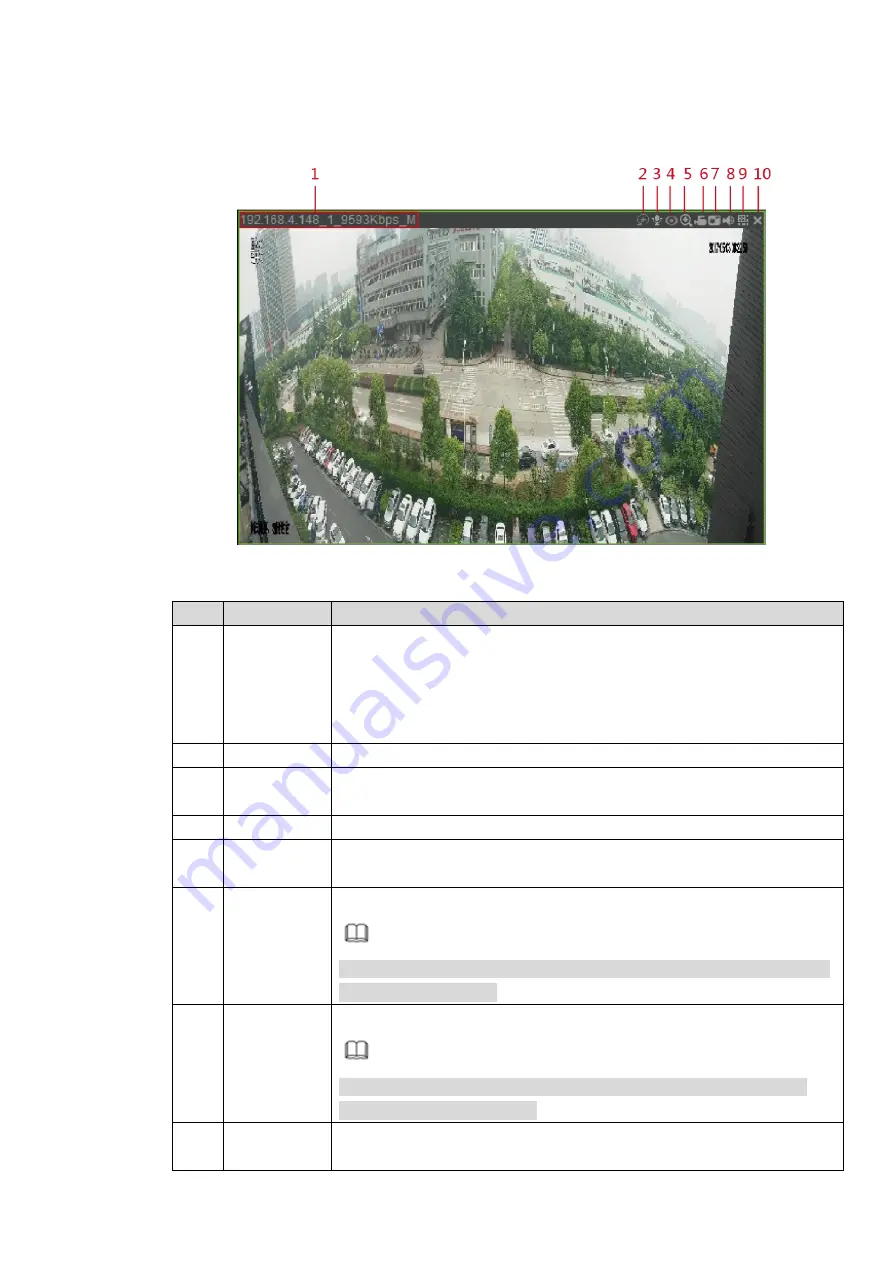
Click any channel to play the real-time monitor window. See Figure 4-15
Figure 4-15
No.
Function
Description
1
Display
device info
The device information is displayed on the top left corner.
When video is available in the monitor window, it displays the
device IP address, channel No., stream, decode type (M for main
stream and S for substream).
If no video is available in the window, it displays no video.
2
Smart track
Click it to view the preset smart track image.
3
Audio talk
Click it to realize the bidirectional communication between the Web and
front-end device.
4
Fisheye
Click it to adjust fisheye mounting mode and display mode.
5
Digital zoom
Select any region in the video window and click this icon to enlarge this
region. Click this icon again and the image returns to the original state.
6
Local record
Click it to start record. Click it again to stop recording.
Note
The default record storage path is C:\RecordDownload. You can enter
Save Path to modify it.
7
snapshot
Click it to snapshot a picture.
Note
The default snapshot storage path is C:\PictureDownload. You can
enter Save Path to modify it.
8
Audio
Open or close audio. If audio is closed, there will be no sound in
monitor.
Содержание ELITE Network IP Series
Страница 1: ...64 Channel 4K Hot Swap NVR NVR ELHS 64 4K DH...
Страница 43: ...Figure 3 14 Step 2 Click Add new holiday button and device displays the following interface See Figure 3 15...
Страница 108: ...Figure 3 92 Figure 3 93...
Страница 131: ...Figure 3 111 Figure 3 112 Figure 3 113...
Страница 144: ...Figure 3 126 Figure 3 127...
Страница 146: ...Figure 3 129 Click draw button to draw the zone See Figure 3 130 Figure 3 130...
Страница 149: ...Figure 3 133 Click Draw button to draw a zone See Figure 3 134 Figure 3 134...
Страница 154: ...Figure 3 139 Click draw button to draw the zone See Figure 3 140...
Страница 165: ...Figure 3 151 Step 2 Add surveillance scene 1 Click Add The Add interface is displayed See Figure 3 152...
Страница 172: ...Figure 3 157 Figure 3 158...
Страница 173: ...Figure 3 159 Figure 3 160...
Страница 176: ...Figure 3 164 Figure 3 165...
Страница 211: ...Figure 3 199...
Страница 218: ...Figure 3 206 Step 2 Click Add user button in Figure 3 206 The interface is shown as in Figure 3 207 Figure 3 207...
Страница 234: ...Figure 3 227 Step 2 Click Add group Enter add group interface See Figure 3 228 Figure 3 228...
Страница 298: ...Figure 4 56 Figure 4 57...
Страница 304: ...Figure 4 62 Figure 4 63...
Страница 305: ...Figure 4 64 Figure 4 65...
Страница 330: ...Figure 4 101 Figure 4 102...
Страница 339: ...Figure 4 115 Figure 4 116...
Страница 359: ...Figure 4 144 Note For admin you can change the email information See Figure 4 145...


