Functions
92
3 E
therC
Assignment
number
Signal name
Function
Signal state
87
R7
These are general signals.
0: OFF
1: ON
88
R8
89
R9
90
R10
91
R11
92
R12
93
R13
94
R14
95
R15
104
EXT1
This is an external latch signal for the touch
probe 1.
0: OFF
1: ON
105
EXT2
This is an external latch signal for the touch
probe 2.
0: OFF
1: ON
•
When the same input signal is assigned to multiple input terminals, the function will be executed if
any of the terminals becomes active.
•
When the HMI input is not assigned to the input terminal, this input will always be 1. If it is
assigned to both direct I/O (DIN0, DIN1) and remote I/O (R-IN0 to R-IN15), the function will be
executed when both of them changes to 1.
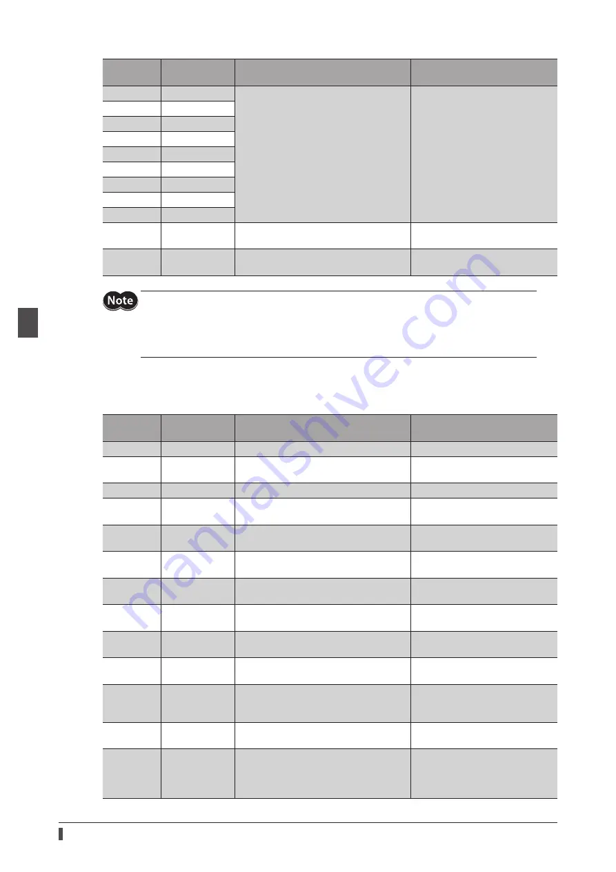
Output signals list
To assign signals via EtherCAT communication, use the "Assignment number” in the table instead of the signal names.
Assignment
number
Signal name
Function
Signal state
0
Not used
Set when the output terminal is not used.
−
1 to 127
Response signal
(Input signal_R)
Output in response to the corresponding
input signal.
0: Input signal is OFF
1: Input signal is ON
128
CONST-OFF
Output an OFF state all the time.
0: OFF
129
ALM-A
Output the alarm status of the driver.
(Normally open)
0: No alarm
1: During alarm generation
130
ALM-B
Output the alarm status of the driver.
(Normally closed)
0: During alarm generation
1: No alarm
131
SYS-RDY
Output when the control power supply of
the driver is turned on.
0: During system preparation
1: System preparation is completed
132
READY
Output when the driver is ready to operate.
0: Operation not possible
1: Ready for operation
134
MOVE
Output when the motor operates.
0: Motor standstill
1: During motor operation
135
INFO
Output the information status of the driver.
0: No information
1: During information generation
136
SYS-BSY
Output when the driver is in an internal
processing state.
0: No internal processing
1: During internal processing
138
IN-POS
Output when positioning operation is
completed. This signal is not output in the
Cyclic synchronous position mode (CSP).
0: During positioning operation
1: Positioning operation is
completed
140
TLC
Output when the output torque reaches
the upper limit value.
0: Within torque range
1: Outside torque range
141
VA
Output when the operating speed reaches
the target speed. This signal is not output
in the Cyclic synchronous position mode
(CSP).
0: Target speed is not reached
1: Target speed is reached
Содержание aSTEP AZ mini Driver
Страница 14: ...14 1 Introduction...
Страница 128: ...128 3 EtherCAT communication...
Страница 146: ...146 4 Object list...
Страница 164: ...164 5 Troubleshooting...
Страница 170: ...170 6 Reference materials...
Страница 171: ...171 6 Reference materials...


