APPENDIX
Page 513
To check the intake air ducts and air cleaner
canister, carefully wipe the inside surfaces with a
rag held by gloved hand. The rag will snag on
pieces that may be imbedded in the inner
surfaces of the ducts and canister. The glove and
rag will protect the hand from being scratched or
cut on any imbedded objects.
Cleaning the Turbocharger Oil
Supply Line, Changing the Engine
Oil and Pre-Lubricating the
Turbocharger Following a Failure
A turbocharger failure can result in debris
contaminating the turbocharger oil supply line. It
is EXTREMELY IMPORTANT to remove, flush
and thoroughly clean the line prior to installing the
replacement turbocharger. Failure to do so can
result in debris from the oil line entering the
replacement turbocharger, causing damage to
the bearings and eventual failure of the
replacement turbocharger.
1. Drain the engine oil.
2. Remove the turbocharger oil supply line and
inspect for kinks or other types of damage.
Replace the line as required. If the oil line is
undamaged, it can be reused.
Stainless steel braided lines can be crimped shut
if not handled or installed correctly. If the steel
braid has been kinked, it pinches the inner tube,
and even if the steel braid is straightened, the
inner tube will remain pinched. Caution must be
used not to bend or twist the steel braided line to
the point where it becomes kinked. If the line has
been kinked, it must be replaced to eliminate
turbocharger damage resulting from restricted oil
flow.
If the oil line is being reused, it must be
flushed with a clean, suitable,
non-flammable solvent. Allow solvent to run
through the line to flush any debris from the
inside, and then blow the line dry with clean
shop air.
3. Mount the turbocharger on the exhaust
manifold, install the oil drain tube and
connect the exhaust pipe. Do not connect
the oil supply line or the inlet air duct to the
turbocharger.
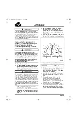
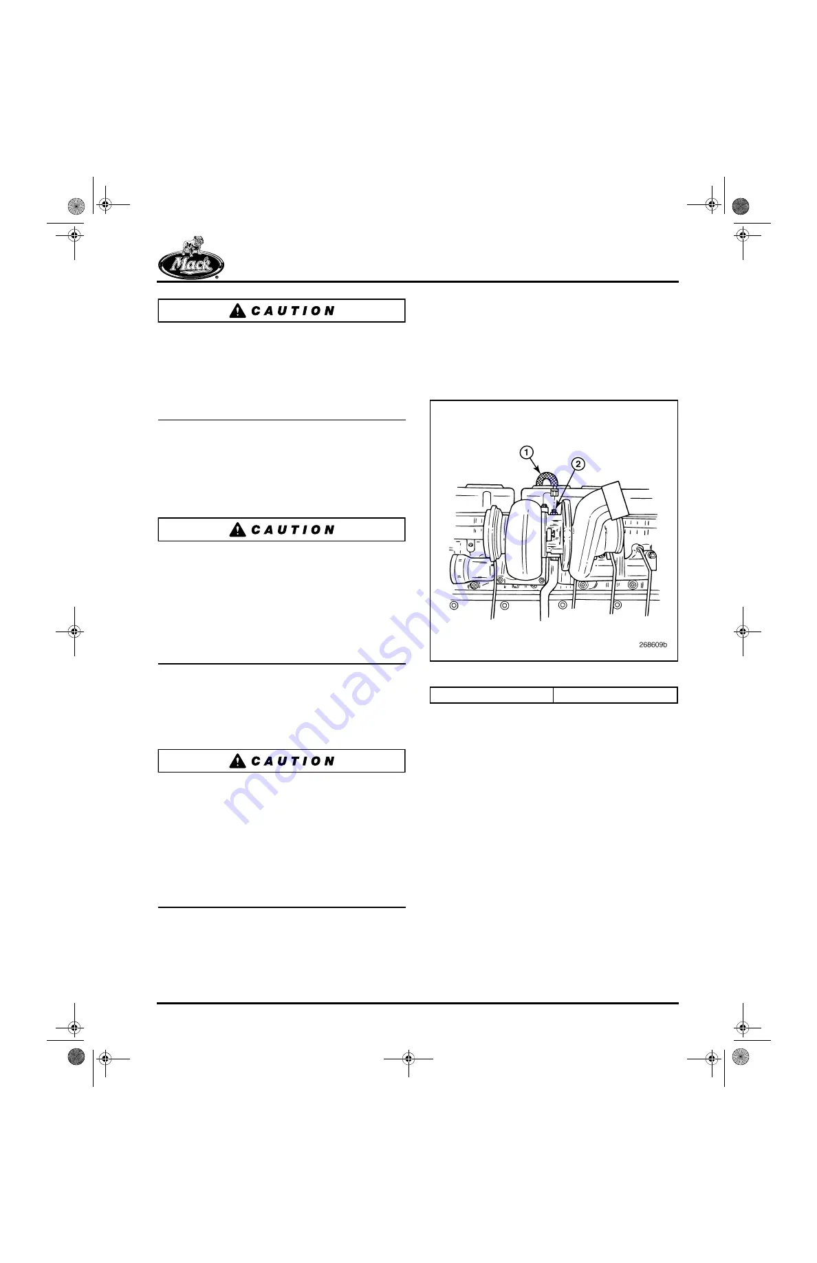
4. Pour clean engine oil into the oil inlet port at
the top of the turbocharger until overflowing.
590
Figure 590 — Turbocharger Oil Inlet Port
5. Spin the compressor wheel by hand several
revolutions and wiggle the shaft back and
forth. This will ensure that oil is distributed
over all bearing surfaces.
6. Install the inlet air duct to the turbocharger,
but do not connect the oil supply line at this
time.
7. Change the spin-on oil filters and the
centrifugal oil filter as outlined in the
Maintenance and Lubrication Manual,
TS494. Be sure to prefill each new spin-on
filter with 2 quarts of new engine oil.
8. Fill the engine crankcase with the proper
specification and grade of engine oil (refer to
the
Maintenance and Lubrication Manual,
TS494, for current engine oil specifications).
1. Oil Inlet Line
2. Oil Inlet Port
appendix.fm Page 513 Tuesday, July 11, 2006 11:18 AM
Содержание ASET AC
Страница 6: ...TABLE OF CONTENTS Page iii TABLE OF CONTENTS 5 111 bk Page iii Monday July 10 2006 2 26 PM...
Страница 14: ...INTRODUCTION Page 1 INTRODUCTION 5 111 bk Page 1 Monday July 10 2006 2 26 PM...
Страница 23: ...Page 10 NOTES 5 111 bk Page 10 Monday July 10 2006 2 26 PM...
Страница 24: ...VISUAL IDENTIFICATION Page 11 VISUAL IDENTIFICATION 5 111 bk Page 11 Monday July 10 2006 2 26 PM...
Страница 28: ...DESCRIPTION AND OPERATION Page 15 DESCRIPTION AND OPERATION 5 111 bk Page 15 Monday July 10 2006 2 26 PM...
Страница 96: ...COMPONENT LOCATOR Page 83 COMPONENT LOCATOR 5 111 bk Page 83 Monday July 10 2006 2 26 PM...
Страница 99: ...Page 86 NOTES 5 111 bk Page 86 Monday July 10 2006 2 26 PM...
Страница 100: ...TROUBLESHOOTING Page 87 TROUBLESHOOTING 5 111 bk Page 87 Monday July 10 2006 2 26 PM...
Страница 140: ...MAINTENANCE Page 127 MAINTENANCE 5 111 bk Page 127 Monday July 10 2006 2 26 PM...
Страница 153: ...Page 140 NOTES 5 111 bk Page 140 Monday July 10 2006 2 26 PM...
Страница 154: ...REPAIR INSTRUCTIONS PART 1 Page 141 REPAIR INSTRUCTIONS PART 1 5 111 bk Page 141 Monday July 10 2006 2 26 PM...
Страница 383: ...Page 370 NOTES 5 111 bk Page 370 Monday July 10 2006 2 26 PM...
Страница 384: ...REPAIR INSTRUCTIONS PART 2 Page 371 REPAIR INSTRUCTIONS PART 2 5 111 bk Page 371 Monday July 10 2006 2 26 PM...
Страница 454: ...REPAIR INSTRUCTIONS PART 3 Page 441 REPAIR INSTRUCTIONS PART 3 5 111 bk Page 441 Monday July 10 2006 2 26 PM...
Страница 479: ...Page 466 NOTES 5 111 bk Page 466 Monday July 10 2006 2 26 PM...
Страница 480: ...SPECIFICATIONS Page 467 SPECIFICATIONS 5 111 bk Page 467 Monday July 10 2006 2 26 PM...
Страница 505: ...Page 492 NOTES 5 111 bk Page 492 Monday July 10 2006 2 26 PM...
Страница 506: ...SCHEMATIC ROUTING DIAGRAMS Page 493 SCHEMATIC ROUTING DIAGRAMS 5 111 bk Page 493 Monday July 10 2006 2 26 PM...
Страница 513: ...Page 500 NOTES 5 111 bk Page 500 Monday July 10 2006 2 26 PM...
Страница 514: ...SPECIAL TOOLS EQUIPMENT Page 501 SPECIAL TOOLS EQUIPMENT 5 111 bk Page 501 Monday July 10 2006 2 26 PM...
Страница 519: ...Page 506 NOTES 5 111 bk Page 506 Monday July 10 2006 2 26 PM...
Страница 520: ...APPENDIX Page 507 APPENDIX 5 111 bk Page 507 Monday July 10 2006 2 26 PM...
Страница 528: ...INDEX Page 515 INDEX Index fm Page 515 Monday July 10 2006 2 48 PM...
Страница 535: ...Page 522 NOTES Index fm Page 522 Monday July 10 2006 2 48 PM...

