


Page 112
TROUBLESHOOTING
The individual boost pressure readings should be
approximately the same as recorded in steps 3
and 4.
5. Compare the maximum boost pressure with
the boost pressures in the table on page
111. A low reading indicates a possible
problem. Readings at sea level should be
within 3 psi of the values shown (at higher
altitudes, slightly lower boost pressure
readings are normal). Readings within 3 psi
of the values shown indicate proper
operation of the engine brake.
Electrical Troubleshooting
ASET™ engines have been equipped with a
V-MAC
®
control feature that automatically
provides a level of protection by activating the
engine brake only after the recommended
minimum oil temperature has been reached. Be
sure that the engine is sufficiently warmed before
conducting tests.
The MACK PowerLeash™ engine brake is
activated by the V-MAC system. When the
ignition switch is turned ON, the engine brake
solenoids are supplied a constant 12-volt direct
current with current flow increasing whenever the
engine brake is activated. To properly diagnose
electrical problems with the brake, an ammeter
may be required.
Some automated manual transmissions prevent
engine brake operation when the transmission is
in neutral.
If insufficient electrical power is reaching the
engine brake, perform the preliminary checks
outlined below. For more information, see the
V-MAC
®
III Service Manual, 8-211.
NO ENGINE BRAKE OPERATION
1. Verify that the clutch pedal is not depressed
and that the clutch switch is working
properly.
2. Check for a blown fuse or circuit breaker.
3. With electrical power OFF, check the control
system for a short to ground. Check systems
separately to isolate where the short is
occurring. If the control system is OK up to
the engine brake valve cover/spacer
connection, measure the resistance to the
solenoid valve. High resistance means an
open circuit in the solenoid or solenoid wire.
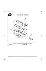
ONLY ONE ROCKER SHAFT OPERATING
1. Determine which rocker shaft is not
operating by closing all the switches and
checking the power at the wires leading to
the solenoid valves (front and rear).
2. Remove the wire to the solenoid valve at the
cylinder head cover/spacer and check for
resistance (refer to the table on page 113).
No reading indicates an open circuit in the
wire or solenoid coil. A low resistance
reading indicates a short to ground in the
solenoid wire or solenoid coil.
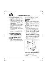
A constant 12-volt low amperage signal is
supplied to the engine brake solenoids by the
V-MAC III module when the ignition switch is
turned on. During an engine braking event,
V-MAC increases the current to the solenoids to
activate the engine brake. The most accurate
method of checking electrical function of the
engine brake solenoid circuits is by using an
ammeter to measure current at the solenoids
when the engine brake is activated. When the
engine brake is activated, current should be
approximately 1.59 amps. For additional
information, consult the V-MAC
®
III Service
Manual, 8-211.
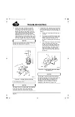
3. Test the solenoid by checking for current
draw and pull-in voltage per specifications
listed in the table on page 113.
5-111.bk Page 112 Monday, July 10, 2006 2:26 PM
Содержание ASET AC
Страница 6: ...TABLE OF CONTENTS Page iii TABLE OF CONTENTS 5 111 bk Page iii Monday July 10 2006 2 26 PM...
Страница 14: ...INTRODUCTION Page 1 INTRODUCTION 5 111 bk Page 1 Monday July 10 2006 2 26 PM...
Страница 23: ...Page 10 NOTES 5 111 bk Page 10 Monday July 10 2006 2 26 PM...
Страница 24: ...VISUAL IDENTIFICATION Page 11 VISUAL IDENTIFICATION 5 111 bk Page 11 Monday July 10 2006 2 26 PM...
Страница 28: ...DESCRIPTION AND OPERATION Page 15 DESCRIPTION AND OPERATION 5 111 bk Page 15 Monday July 10 2006 2 26 PM...
Страница 96: ...COMPONENT LOCATOR Page 83 COMPONENT LOCATOR 5 111 bk Page 83 Monday July 10 2006 2 26 PM...
Страница 99: ...Page 86 NOTES 5 111 bk Page 86 Monday July 10 2006 2 26 PM...
Страница 100: ...TROUBLESHOOTING Page 87 TROUBLESHOOTING 5 111 bk Page 87 Monday July 10 2006 2 26 PM...
Страница 140: ...MAINTENANCE Page 127 MAINTENANCE 5 111 bk Page 127 Monday July 10 2006 2 26 PM...
Страница 153: ...Page 140 NOTES 5 111 bk Page 140 Monday July 10 2006 2 26 PM...
Страница 154: ...REPAIR INSTRUCTIONS PART 1 Page 141 REPAIR INSTRUCTIONS PART 1 5 111 bk Page 141 Monday July 10 2006 2 26 PM...
Страница 383: ...Page 370 NOTES 5 111 bk Page 370 Monday July 10 2006 2 26 PM...
Страница 384: ...REPAIR INSTRUCTIONS PART 2 Page 371 REPAIR INSTRUCTIONS PART 2 5 111 bk Page 371 Monday July 10 2006 2 26 PM...
Страница 454: ...REPAIR INSTRUCTIONS PART 3 Page 441 REPAIR INSTRUCTIONS PART 3 5 111 bk Page 441 Monday July 10 2006 2 26 PM...
Страница 479: ...Page 466 NOTES 5 111 bk Page 466 Monday July 10 2006 2 26 PM...
Страница 480: ...SPECIFICATIONS Page 467 SPECIFICATIONS 5 111 bk Page 467 Monday July 10 2006 2 26 PM...
Страница 505: ...Page 492 NOTES 5 111 bk Page 492 Monday July 10 2006 2 26 PM...
Страница 506: ...SCHEMATIC ROUTING DIAGRAMS Page 493 SCHEMATIC ROUTING DIAGRAMS 5 111 bk Page 493 Monday July 10 2006 2 26 PM...
Страница 513: ...Page 500 NOTES 5 111 bk Page 500 Monday July 10 2006 2 26 PM...
Страница 514: ...SPECIAL TOOLS EQUIPMENT Page 501 SPECIAL TOOLS EQUIPMENT 5 111 bk Page 501 Monday July 10 2006 2 26 PM...
Страница 519: ...Page 506 NOTES 5 111 bk Page 506 Monday July 10 2006 2 26 PM...
Страница 520: ...APPENDIX Page 507 APPENDIX 5 111 bk Page 507 Monday July 10 2006 2 26 PM...
Страница 528: ...INDEX Page 515 INDEX Index fm Page 515 Monday July 10 2006 2 48 PM...
Страница 535: ...Page 522 NOTES Index fm Page 522 Monday July 10 2006 2 48 PM...