DESCRIPTION AND OPERATION
Page 49
47
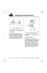
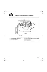
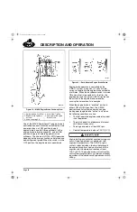
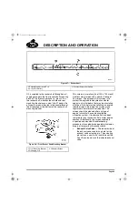
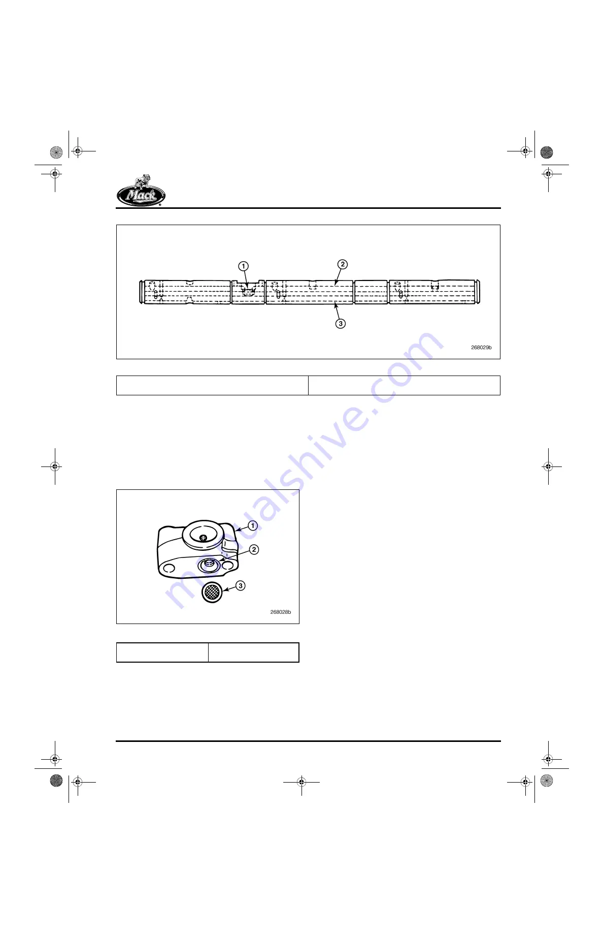
Figure 47 — Rocker Shaft
Oil is supplied to the rocker shaft through an oil
supply passage in the front rocker shaft mounting
bracket. This mounting bracket is “press-fit” on
the rocker shaft, whereas the middle and rear
mounting brackets are a new “slip-fit” design. An
oil supply screen is located in the counterbore of
the oil passage at the bottom of the rocker shaft
mounting bracket.
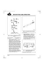
48
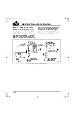
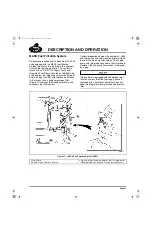
Figure 48 — Front Rocker Shaft Mounting Bracket
This screen is a relatively fine (100 x 100 mesh)
stainless steel screen with a nominal rating of
40 microns. The purpose of this screen is to
protect the engine brake hydraulic actuator
against any initial debris that may be circulating
with the oil at initial start-up following an engine
rebuild or repair. Servicing the screen at any
regular service interval is not required. The
screen should be cleaned after any type of
engine failure that has contaminated the
lubrication system, if rocker shafts have been
removed for any reason or after a major engine
overhaul. Additionally, the screen should be
inspected and cleaned if troubleshooting
procedures for engine brake operation indicate a
drop in oil pressure at the rocker shafts.
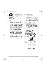
앫
Exhaust Valve Yoke
— The inboard side of
the exhaust yokes contains a hole for the
exhaust valve actuating pin. The actuating
pin rests on a cap that is installed over the
tip of the valve stem on the inboard exhaust
valve.
1. Engine Brake Solenoid Port
2. Control Oil Gallery
3. Constant Supply Oil Gallery
1. Front Mounting Bracket
2. Oil Supply Port
3. Oil Supply Screen
5-111.bk Page 49 Monday, July 10, 2006 2:26 PM
Содержание ASET AC
Страница 6: ...TABLE OF CONTENTS Page iii TABLE OF CONTENTS 5 111 bk Page iii Monday July 10 2006 2 26 PM...
Страница 14: ...INTRODUCTION Page 1 INTRODUCTION 5 111 bk Page 1 Monday July 10 2006 2 26 PM...
Страница 23: ...Page 10 NOTES 5 111 bk Page 10 Monday July 10 2006 2 26 PM...
Страница 24: ...VISUAL IDENTIFICATION Page 11 VISUAL IDENTIFICATION 5 111 bk Page 11 Monday July 10 2006 2 26 PM...
Страница 28: ...DESCRIPTION AND OPERATION Page 15 DESCRIPTION AND OPERATION 5 111 bk Page 15 Monday July 10 2006 2 26 PM...
Страница 96: ...COMPONENT LOCATOR Page 83 COMPONENT LOCATOR 5 111 bk Page 83 Monday July 10 2006 2 26 PM...
Страница 99: ...Page 86 NOTES 5 111 bk Page 86 Monday July 10 2006 2 26 PM...
Страница 100: ...TROUBLESHOOTING Page 87 TROUBLESHOOTING 5 111 bk Page 87 Monday July 10 2006 2 26 PM...
Страница 140: ...MAINTENANCE Page 127 MAINTENANCE 5 111 bk Page 127 Monday July 10 2006 2 26 PM...
Страница 153: ...Page 140 NOTES 5 111 bk Page 140 Monday July 10 2006 2 26 PM...
Страница 154: ...REPAIR INSTRUCTIONS PART 1 Page 141 REPAIR INSTRUCTIONS PART 1 5 111 bk Page 141 Monday July 10 2006 2 26 PM...
Страница 383: ...Page 370 NOTES 5 111 bk Page 370 Monday July 10 2006 2 26 PM...
Страница 384: ...REPAIR INSTRUCTIONS PART 2 Page 371 REPAIR INSTRUCTIONS PART 2 5 111 bk Page 371 Monday July 10 2006 2 26 PM...
Страница 454: ...REPAIR INSTRUCTIONS PART 3 Page 441 REPAIR INSTRUCTIONS PART 3 5 111 bk Page 441 Monday July 10 2006 2 26 PM...
Страница 479: ...Page 466 NOTES 5 111 bk Page 466 Monday July 10 2006 2 26 PM...
Страница 480: ...SPECIFICATIONS Page 467 SPECIFICATIONS 5 111 bk Page 467 Monday July 10 2006 2 26 PM...
Страница 505: ...Page 492 NOTES 5 111 bk Page 492 Monday July 10 2006 2 26 PM...
Страница 506: ...SCHEMATIC ROUTING DIAGRAMS Page 493 SCHEMATIC ROUTING DIAGRAMS 5 111 bk Page 493 Monday July 10 2006 2 26 PM...
Страница 513: ...Page 500 NOTES 5 111 bk Page 500 Monday July 10 2006 2 26 PM...
Страница 514: ...SPECIAL TOOLS EQUIPMENT Page 501 SPECIAL TOOLS EQUIPMENT 5 111 bk Page 501 Monday July 10 2006 2 26 PM...
Страница 519: ...Page 506 NOTES 5 111 bk Page 506 Monday July 10 2006 2 26 PM...
Страница 520: ...APPENDIX Page 507 APPENDIX 5 111 bk Page 507 Monday July 10 2006 2 26 PM...
Страница 528: ...INDEX Page 515 INDEX Index fm Page 515 Monday July 10 2006 2 48 PM...
Страница 535: ...Page 522 NOTES Index fm Page 522 Monday July 10 2006 2 48 PM...

