Page 190
REPAIR INSTRUCTIONS, PART 1
Cylinder Sleeve Counterbore
[211 DB]
INSPECTION AND REPAIR
If the cylinder block deck is resurfaced, the
cylinder sleeve counterbore depth must be recut
to specification. If the cylinder block deck was not
resurfaced but cylinder sleeve counterbore
surface shows excessive pitting or erosion, recut
the counterbore as required.
Use shims to re-establish the correct liner flange
height. Shims are available in the following
thicknesses: 0.002, 0.003, 0.004, 0.010, 0.012,
0.014, 0.020, 0.031 and 0.042 inch thicknesses,
and are to be used as a single shim repair
whenever possible.
If it is necessary to use more than a single shim,
use the fewest shims possible. Also because very
thin shims can be displaced, avoid the use of
0.002, 0.003 and 0.004 shim sizes whenever
possible.
Due to manufacturing tolerance differences, all
shims should be measured to determine their
actual shim thickness dimension before recutting
the sleeve seat.
To resurface the cylinder sleeve counterbore
area of the cylinder block, use counterbore tool
PT2210 with counterbore cutter plate
PT2210-3A.
This procedure can be performed either in or out
of the chassis. If performing the procedure in the
chassis, be sure to cover the crankshaft and any
holes in the cylinder block to prevent
contamination from machining chips.
1. Thoroughly clean and inspect the sleeve
seating surface on the cylinder block
counterbore flange. Visually identify the
counterbore flange that has the most severe
pitting and recut it first to determine if the
block will be within the specified recut limits.
Do not cut seats deeper than 4.040 inches
(102.616 mm). If the maximum recut dimension is
reached and visible pitting remains, the pitting is
acceptable as long as there is not a complete
leak path all the way across the cylinder block
sleeve seat surface.
2. Make sure that the top of the deck is clean
and free of burrs. Use a finish mill file and
crocus cloth, if necessary, to create a
smooth, flat surface for positioning the tool.
3. Using compressed air, thoroughly remove all
debris.
Universal dial depth gauge PT5025, with a
three-inch stylus extension PT5025-11, is
recommended for measuring the counterbore.
4. Measure and record the counterbore in four
places, 90 degrees apart. Using a depth
gauge with a three-inch extension, mark the
shallowest point. Subtract the lowest
number from the highest number. This is the
minimum amount to be machined for
cleanup. Additional machining may be
required depending on the size of any
remaining pits.
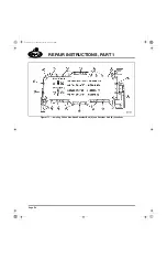
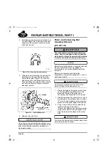
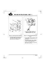
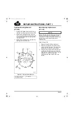
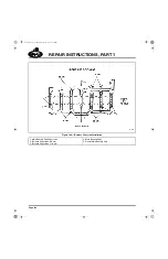
SETTING UP COUNTERBORE TOOL PT2210
WITH CUTTER PLATE PT2210-3A
Refer to Figure 190.
1. Loosen the two cutter bit hold-down
capscrews. Install the cutter bit into the
cutter plate PT2210-3A by turning the cutter
bit adjuster counterclockwise. The cutter bit
face must be positioned for a clockwise
rotation cut.
Do not tighten the cutter bit hold-down cap.
The cutter point should not extend beyond the
outer edge of the cutter plate. If the cutter bit
does stick out, damage to the bit will occur when
installing the counterbore tool on the cylinder
block.
5-111.bk Page 190 Monday, July 10, 2006 2:26 PM
Содержание ASET AC
Страница 6: ...TABLE OF CONTENTS Page iii TABLE OF CONTENTS 5 111 bk Page iii Monday July 10 2006 2 26 PM...
Страница 14: ...INTRODUCTION Page 1 INTRODUCTION 5 111 bk Page 1 Monday July 10 2006 2 26 PM...
Страница 23: ...Page 10 NOTES 5 111 bk Page 10 Monday July 10 2006 2 26 PM...
Страница 24: ...VISUAL IDENTIFICATION Page 11 VISUAL IDENTIFICATION 5 111 bk Page 11 Monday July 10 2006 2 26 PM...
Страница 28: ...DESCRIPTION AND OPERATION Page 15 DESCRIPTION AND OPERATION 5 111 bk Page 15 Monday July 10 2006 2 26 PM...
Страница 96: ...COMPONENT LOCATOR Page 83 COMPONENT LOCATOR 5 111 bk Page 83 Monday July 10 2006 2 26 PM...
Страница 99: ...Page 86 NOTES 5 111 bk Page 86 Monday July 10 2006 2 26 PM...
Страница 100: ...TROUBLESHOOTING Page 87 TROUBLESHOOTING 5 111 bk Page 87 Monday July 10 2006 2 26 PM...
Страница 140: ...MAINTENANCE Page 127 MAINTENANCE 5 111 bk Page 127 Monday July 10 2006 2 26 PM...
Страница 153: ...Page 140 NOTES 5 111 bk Page 140 Monday July 10 2006 2 26 PM...
Страница 154: ...REPAIR INSTRUCTIONS PART 1 Page 141 REPAIR INSTRUCTIONS PART 1 5 111 bk Page 141 Monday July 10 2006 2 26 PM...
Страница 383: ...Page 370 NOTES 5 111 bk Page 370 Monday July 10 2006 2 26 PM...
Страница 384: ...REPAIR INSTRUCTIONS PART 2 Page 371 REPAIR INSTRUCTIONS PART 2 5 111 bk Page 371 Monday July 10 2006 2 26 PM...
Страница 454: ...REPAIR INSTRUCTIONS PART 3 Page 441 REPAIR INSTRUCTIONS PART 3 5 111 bk Page 441 Monday July 10 2006 2 26 PM...
Страница 479: ...Page 466 NOTES 5 111 bk Page 466 Monday July 10 2006 2 26 PM...
Страница 480: ...SPECIFICATIONS Page 467 SPECIFICATIONS 5 111 bk Page 467 Monday July 10 2006 2 26 PM...
Страница 505: ...Page 492 NOTES 5 111 bk Page 492 Monday July 10 2006 2 26 PM...
Страница 506: ...SCHEMATIC ROUTING DIAGRAMS Page 493 SCHEMATIC ROUTING DIAGRAMS 5 111 bk Page 493 Monday July 10 2006 2 26 PM...
Страница 513: ...Page 500 NOTES 5 111 bk Page 500 Monday July 10 2006 2 26 PM...
Страница 514: ...SPECIAL TOOLS EQUIPMENT Page 501 SPECIAL TOOLS EQUIPMENT 5 111 bk Page 501 Monday July 10 2006 2 26 PM...
Страница 519: ...Page 506 NOTES 5 111 bk Page 506 Monday July 10 2006 2 26 PM...
Страница 520: ...APPENDIX Page 507 APPENDIX 5 111 bk Page 507 Monday July 10 2006 2 26 PM...
Страница 528: ...INDEX Page 515 INDEX Index fm Page 515 Monday July 10 2006 2 48 PM...
Страница 535: ...Page 522 NOTES Index fm Page 522 Monday July 10 2006 2 48 PM...

