Page 376
REPAIR INSTRUCTIONS, PART 2
CAMSHAFT REPLACEMENT
(IN-CHASSIS)
[213 CH]
Preliminary Steps
It is a good practice to steam clean the engine to
remove road grime, grease and oil before starting
work. Steam cleaning the engine allows more
detailed inspection and improved workmanship.
Care must be used to keep moisture from
entering the air intake system. If moisture does
enter the system, make sure it is removed (dried
out) immediately, to prevent damage to the
engine components.
The preliminary steps for replacing the camshaft
will vary depending on the chassis configuration
and engine model. As such, these steps are
general in nature. Begin the operation by
disconnecting the battery and draining all fluids
from the engine. Then, remove the hood and
fender assembly, radiator, engine
accessories/drives, ducts, EGR components
(AC engine only), electronic unit pump
assemblies and roller tappets, valve covers,
engine brake assemblies (if equipped), rocker
shaft assemblies, push rods, water
pump/housing, oil pan and front cover, etc. Refer
to the appropriate sections in this manual for
replacement procedures for the various engine
components.
The cylinder heads will remain installed. Removal
of the cylinder heads will only be necessary if it is
determined that the H-ring(s) must be replaced.
Camshaft/Lifter Removal
앫
When removing or installing the camshaft,
first remove the idler gear and hub. It is
easier to remove the camshaft guide from
the camshaft (after installation) when the
idler gear has been removed and alignment
of the timing marks is not being attempted at
the same time. The final step in the process
is to reinstall the idler gear.
앫
When preparing to install the camshaft
removal/installation tool (tool No. J 41682),
the engine should be rotated so that the cam
timing marks are approximately at the
1–2 o’clock position when viewed from the
front. With the engine in this position,
adequate clearance will be provided to
install the tool.
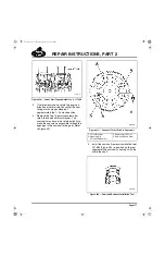
With the engine in the chassis, the valve lifters
must be held in the UP position, using tappet
holder J 37720-C in combination with J 42425.
1. Insert the tappet holder in the lifter bore so
that the magnetic head of the tool holds the
lifter in position. Check to see if the tool has
captured the valve lifter by drawing upward
on the tool. A resistance will be felt that
cannot be felt if the magnet has contacted
something other than a valve lifter.
2. Secure the lifter in the UP position with
grommets provided with the tappet holders.
The holding tool shafts of two adjacent valve
lifters can be prevented from dropping by
wrapping a rubber band around the two
shafts. This draws the shafts together and
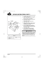
holds them in position. Refer to Figure 450.
5-111.bk Page 376 Monday, July 10, 2006 2:26 PM
Содержание ASET AC
Страница 6: ...TABLE OF CONTENTS Page iii TABLE OF CONTENTS 5 111 bk Page iii Monday July 10 2006 2 26 PM...
Страница 14: ...INTRODUCTION Page 1 INTRODUCTION 5 111 bk Page 1 Monday July 10 2006 2 26 PM...
Страница 23: ...Page 10 NOTES 5 111 bk Page 10 Monday July 10 2006 2 26 PM...
Страница 24: ...VISUAL IDENTIFICATION Page 11 VISUAL IDENTIFICATION 5 111 bk Page 11 Monday July 10 2006 2 26 PM...
Страница 28: ...DESCRIPTION AND OPERATION Page 15 DESCRIPTION AND OPERATION 5 111 bk Page 15 Monday July 10 2006 2 26 PM...
Страница 96: ...COMPONENT LOCATOR Page 83 COMPONENT LOCATOR 5 111 bk Page 83 Monday July 10 2006 2 26 PM...
Страница 99: ...Page 86 NOTES 5 111 bk Page 86 Monday July 10 2006 2 26 PM...
Страница 100: ...TROUBLESHOOTING Page 87 TROUBLESHOOTING 5 111 bk Page 87 Monday July 10 2006 2 26 PM...
Страница 140: ...MAINTENANCE Page 127 MAINTENANCE 5 111 bk Page 127 Monday July 10 2006 2 26 PM...
Страница 153: ...Page 140 NOTES 5 111 bk Page 140 Monday July 10 2006 2 26 PM...
Страница 154: ...REPAIR INSTRUCTIONS PART 1 Page 141 REPAIR INSTRUCTIONS PART 1 5 111 bk Page 141 Monday July 10 2006 2 26 PM...
Страница 383: ...Page 370 NOTES 5 111 bk Page 370 Monday July 10 2006 2 26 PM...
Страница 384: ...REPAIR INSTRUCTIONS PART 2 Page 371 REPAIR INSTRUCTIONS PART 2 5 111 bk Page 371 Monday July 10 2006 2 26 PM...
Страница 454: ...REPAIR INSTRUCTIONS PART 3 Page 441 REPAIR INSTRUCTIONS PART 3 5 111 bk Page 441 Monday July 10 2006 2 26 PM...
Страница 479: ...Page 466 NOTES 5 111 bk Page 466 Monday July 10 2006 2 26 PM...
Страница 480: ...SPECIFICATIONS Page 467 SPECIFICATIONS 5 111 bk Page 467 Monday July 10 2006 2 26 PM...
Страница 505: ...Page 492 NOTES 5 111 bk Page 492 Monday July 10 2006 2 26 PM...
Страница 506: ...SCHEMATIC ROUTING DIAGRAMS Page 493 SCHEMATIC ROUTING DIAGRAMS 5 111 bk Page 493 Monday July 10 2006 2 26 PM...
Страница 513: ...Page 500 NOTES 5 111 bk Page 500 Monday July 10 2006 2 26 PM...
Страница 514: ...SPECIAL TOOLS EQUIPMENT Page 501 SPECIAL TOOLS EQUIPMENT 5 111 bk Page 501 Monday July 10 2006 2 26 PM...
Страница 519: ...Page 506 NOTES 5 111 bk Page 506 Monday July 10 2006 2 26 PM...
Страница 520: ...APPENDIX Page 507 APPENDIX 5 111 bk Page 507 Monday July 10 2006 2 26 PM...
Страница 528: ...INDEX Page 515 INDEX Index fm Page 515 Monday July 10 2006 2 48 PM...
Страница 535: ...Page 522 NOTES Index fm Page 522 Monday July 10 2006 2 48 PM...

