Page 404
REPAIR INSTRUCTIONS, PART 2
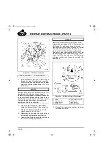
Early-production engines will use coupling
adapters in combination with the one-piece cool
tube assembly. On vehicles so equipped:
앫
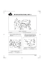
Loosen and remove the clamp from the cool
tube coupling hose adapter at the EGR
cooler tube mounting flange. Remove and
discard the wire-mesh seal. Inspect the
adapter for corrosion or damage and replace
as required.
앫
Loosen and remove the clamp from the cool
tube coupling hose adapter at the EGR
mixer tube. Remove and discard the
wire-mesh seal. Inspect the adapter and
replace as required.
Do not attempt to remove the EGR MASS Flow
sensors from the tube. The sensors are an
integral part of the tube and must be replaced as
an assembly.
HOT TUBE REMOVAL
If the hot tube is to be removed, the cool tube
clamp bracket and spacer studs must also be
removed from the top of the EGR valve. This is
necessary to loosen the EGR valve on its
mounting for reinstallation of the hot tube.
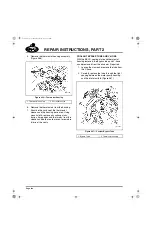
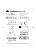
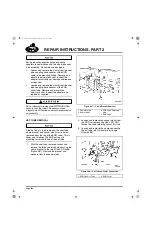
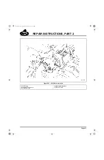
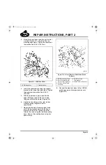
1. With the cool tube removed, loosen and
remove the three retaining nuts securing the
clamp bracket to the top of the EGR valve
(Figure 487). Remove the bracket and
washers from the spacer studs.
487
Figure 487 — Clamp Bracket Removal
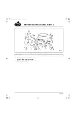
2. Loosen and remove the spacer studs from
the EGR valve mounting studs. DO NOT
loosen the valve retaining nuts at this time.
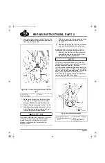
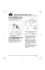
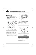
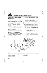
3. Loosen and remove the clamp connecting
the hot tube-to-EGR cooler inlet flange
(Figure 488).
488
Figure 488 — Hot Tube-to-Cooler Connection
1. Clamp Bracket
2. Spacer Studs
3. EGR Valve Retaining
Nuts
4. EGR Valve
1. EGR Gas Hot Tube
2. EGR Cooler
5-111.bk Page 404 Monday, July 10, 2006 2:26 PM
Содержание ASET AC
Страница 6: ...TABLE OF CONTENTS Page iii TABLE OF CONTENTS 5 111 bk Page iii Monday July 10 2006 2 26 PM...
Страница 14: ...INTRODUCTION Page 1 INTRODUCTION 5 111 bk Page 1 Monday July 10 2006 2 26 PM...
Страница 23: ...Page 10 NOTES 5 111 bk Page 10 Monday July 10 2006 2 26 PM...
Страница 24: ...VISUAL IDENTIFICATION Page 11 VISUAL IDENTIFICATION 5 111 bk Page 11 Monday July 10 2006 2 26 PM...
Страница 28: ...DESCRIPTION AND OPERATION Page 15 DESCRIPTION AND OPERATION 5 111 bk Page 15 Monday July 10 2006 2 26 PM...
Страница 96: ...COMPONENT LOCATOR Page 83 COMPONENT LOCATOR 5 111 bk Page 83 Monday July 10 2006 2 26 PM...
Страница 99: ...Page 86 NOTES 5 111 bk Page 86 Monday July 10 2006 2 26 PM...
Страница 100: ...TROUBLESHOOTING Page 87 TROUBLESHOOTING 5 111 bk Page 87 Monday July 10 2006 2 26 PM...
Страница 140: ...MAINTENANCE Page 127 MAINTENANCE 5 111 bk Page 127 Monday July 10 2006 2 26 PM...
Страница 153: ...Page 140 NOTES 5 111 bk Page 140 Monday July 10 2006 2 26 PM...
Страница 154: ...REPAIR INSTRUCTIONS PART 1 Page 141 REPAIR INSTRUCTIONS PART 1 5 111 bk Page 141 Monday July 10 2006 2 26 PM...
Страница 383: ...Page 370 NOTES 5 111 bk Page 370 Monday July 10 2006 2 26 PM...
Страница 384: ...REPAIR INSTRUCTIONS PART 2 Page 371 REPAIR INSTRUCTIONS PART 2 5 111 bk Page 371 Monday July 10 2006 2 26 PM...
Страница 454: ...REPAIR INSTRUCTIONS PART 3 Page 441 REPAIR INSTRUCTIONS PART 3 5 111 bk Page 441 Monday July 10 2006 2 26 PM...
Страница 479: ...Page 466 NOTES 5 111 bk Page 466 Monday July 10 2006 2 26 PM...
Страница 480: ...SPECIFICATIONS Page 467 SPECIFICATIONS 5 111 bk Page 467 Monday July 10 2006 2 26 PM...
Страница 505: ...Page 492 NOTES 5 111 bk Page 492 Monday July 10 2006 2 26 PM...
Страница 506: ...SCHEMATIC ROUTING DIAGRAMS Page 493 SCHEMATIC ROUTING DIAGRAMS 5 111 bk Page 493 Monday July 10 2006 2 26 PM...
Страница 513: ...Page 500 NOTES 5 111 bk Page 500 Monday July 10 2006 2 26 PM...
Страница 514: ...SPECIAL TOOLS EQUIPMENT Page 501 SPECIAL TOOLS EQUIPMENT 5 111 bk Page 501 Monday July 10 2006 2 26 PM...
Страница 519: ...Page 506 NOTES 5 111 bk Page 506 Monday July 10 2006 2 26 PM...
Страница 520: ...APPENDIX Page 507 APPENDIX 5 111 bk Page 507 Monday July 10 2006 2 26 PM...
Страница 528: ...INDEX Page 515 INDEX Index fm Page 515 Monday July 10 2006 2 48 PM...
Страница 535: ...Page 522 NOTES Index fm Page 522 Monday July 10 2006 2 48 PM...

