Page 428
REPAIR INSTRUCTIONS, PART 2
519
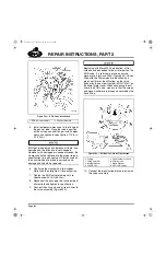
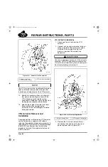
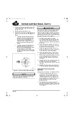
Figure 519 — Actuator Line Connections
The VTG system must be re-calibrated for proper
open and closed vane-position voltages after
installation and adjustment of the VTG actuator.
14. Reinstall all accessory items, ducting, etc.,
that were removed to gain access to the
VTG turbocharger and related system
components. Replace all fluids drained from
the engine and reconnect the batteries.
15. Operate the engine at low idle for at least
three minutes after completing the
installation of the turbocharger and before
driving the vehicle.
VTG Actuator Removal and
Installation
A damaged and/or malfunctioning VTG actuator
can be serviced as a separate unit without
replacing the complete turbocharger assembly. A
replacement VTG actuator kit is available through
the MACK Parts System. Use the following
procedure to reinstall the original actuator or to
install a new unit.
VTG ACTUATOR REMOVAL
1. Disconnect the air line from the VTG
actuator.
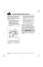
2. Connect a shop air pressure line to the air
fitting at the top of the actuator assembly
(Figure 520) and apply 40–60 psi air
pressure to extend the actuator rod
downward.
Use care in applying air pressure to the actuator
assembly. DO NOT apply pressure greater than
100 psi to the actuator at any time, as damage to
the actuator diaphragm may result.
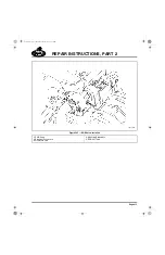
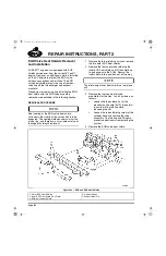
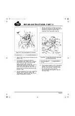
520
Figure 520 — Air Pressure Application
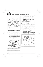
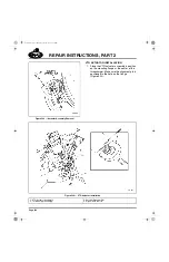
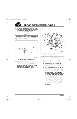
3. Remove the C-clip and remove the pin
connecting the actuator rod to the vane
operating lever clevis (Figure 521).
1. Actuator Air Line
2. VTG Position Sensor
3. VTG Actuator Assembly
1. Shop Air Supply Line
2. VTG Actuator Assembly
5-111.bk Page 428 Monday, July 10, 2006 2:26 PM
Содержание ASET AC
Страница 6: ...TABLE OF CONTENTS Page iii TABLE OF CONTENTS 5 111 bk Page iii Monday July 10 2006 2 26 PM...
Страница 14: ...INTRODUCTION Page 1 INTRODUCTION 5 111 bk Page 1 Monday July 10 2006 2 26 PM...
Страница 23: ...Page 10 NOTES 5 111 bk Page 10 Monday July 10 2006 2 26 PM...
Страница 24: ...VISUAL IDENTIFICATION Page 11 VISUAL IDENTIFICATION 5 111 bk Page 11 Monday July 10 2006 2 26 PM...
Страница 28: ...DESCRIPTION AND OPERATION Page 15 DESCRIPTION AND OPERATION 5 111 bk Page 15 Monday July 10 2006 2 26 PM...
Страница 96: ...COMPONENT LOCATOR Page 83 COMPONENT LOCATOR 5 111 bk Page 83 Monday July 10 2006 2 26 PM...
Страница 99: ...Page 86 NOTES 5 111 bk Page 86 Monday July 10 2006 2 26 PM...
Страница 100: ...TROUBLESHOOTING Page 87 TROUBLESHOOTING 5 111 bk Page 87 Monday July 10 2006 2 26 PM...
Страница 140: ...MAINTENANCE Page 127 MAINTENANCE 5 111 bk Page 127 Monday July 10 2006 2 26 PM...
Страница 153: ...Page 140 NOTES 5 111 bk Page 140 Monday July 10 2006 2 26 PM...
Страница 154: ...REPAIR INSTRUCTIONS PART 1 Page 141 REPAIR INSTRUCTIONS PART 1 5 111 bk Page 141 Monday July 10 2006 2 26 PM...
Страница 383: ...Page 370 NOTES 5 111 bk Page 370 Monday July 10 2006 2 26 PM...
Страница 384: ...REPAIR INSTRUCTIONS PART 2 Page 371 REPAIR INSTRUCTIONS PART 2 5 111 bk Page 371 Monday July 10 2006 2 26 PM...
Страница 454: ...REPAIR INSTRUCTIONS PART 3 Page 441 REPAIR INSTRUCTIONS PART 3 5 111 bk Page 441 Monday July 10 2006 2 26 PM...
Страница 479: ...Page 466 NOTES 5 111 bk Page 466 Monday July 10 2006 2 26 PM...
Страница 480: ...SPECIFICATIONS Page 467 SPECIFICATIONS 5 111 bk Page 467 Monday July 10 2006 2 26 PM...
Страница 505: ...Page 492 NOTES 5 111 bk Page 492 Monday July 10 2006 2 26 PM...
Страница 506: ...SCHEMATIC ROUTING DIAGRAMS Page 493 SCHEMATIC ROUTING DIAGRAMS 5 111 bk Page 493 Monday July 10 2006 2 26 PM...
Страница 513: ...Page 500 NOTES 5 111 bk Page 500 Monday July 10 2006 2 26 PM...
Страница 514: ...SPECIAL TOOLS EQUIPMENT Page 501 SPECIAL TOOLS EQUIPMENT 5 111 bk Page 501 Monday July 10 2006 2 26 PM...
Страница 519: ...Page 506 NOTES 5 111 bk Page 506 Monday July 10 2006 2 26 PM...
Страница 520: ...APPENDIX Page 507 APPENDIX 5 111 bk Page 507 Monday July 10 2006 2 26 PM...
Страница 528: ...INDEX Page 515 INDEX Index fm Page 515 Monday July 10 2006 2 48 PM...
Страница 535: ...Page 522 NOTES Index fm Page 522 Monday July 10 2006 2 48 PM...

