REPAIR INSTRUCTIONS, PART 3
Page 443
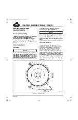
There are 12 clutch mounting bolt holes in the
flywheel, but only 8 of these holes are used to
mount the clutch. Every third bolt hole, for a total
of four, is not used. These holes are in an open
area between the clutch mounting flanges. The
unused holes are easy to see through the timing
access hole in the flywheel housing. The bolt
holes where there are clutch mounting bolts are
more difficult to see because the clutch mounting
bolt head is somewhat rearward of the timing
access opening. To aid in counting the clutch
mounting bolt/bolt holes, keep in mind that there
is slightly over four inches between one bolt hole
and the next. Locating the clutch mounting bolts
may be made easier by removing the bell housing
inspection cover and viewing or feeling for the
bolts through the access hole.
After verifying that there is a clutch mounting
bolt/bolt hole in line with the TC mark, the next
step is to find the three locations where the valve
adjustment marks should be. Put a temporary
mark (chalk, grease pencil, paint, etc.) at each of
the three locations. Proceed as follows:
1. Beginning with the TC mark aligned with the
timing pointer, rotate the engine in the
direction of normal rotation
(counterclockwise, viewed from rear) to the
next clutch mounting bolt/bolt hole.
Temporarily mark this location for
cylinders 1 and 6.
2. Continue rotating the engine in the normal
direction and count the clutch mounting
bolt/bolt holes as they pass the timing
access opening. At the fourth mounting
bolt/bolt hole, make a temporary mark on the
flywheel for cylinders 2 and 5.
3. Rotate the engine another four mounting
bolt/bolt holes and make a temporary mark
on the flywheel for cylinders 3 and 4.
4. Rotate the engine another three clutch
mounting bolt/bolt holes and verify that the
flywheel is at the TC mark. Then, rotate the
engine one more bolt/bolt hole and verify
that the flywheel is at the temporary mark
made for cylinders 1 and 6.
5. Permanently mark the flywheel at this
location for cylinders 1 and 6. To gain
access, rotate the engine slightly so that the
area to be marked is either to the right or left
side of the timing pointer. Place a chisel
mark directly in line with the clutch mounting
bolt/bolt hole. Then, stamp or electric-etch
the cylinder numbers on either side of the
chisel mark.
6. Rotate the engine to the remaining locations
and make sure to count the clutch mounting
bolt/bolt holes to verify the locations of the
temporary markings. Once verified,
permanently mark each location as
described.
NON-TYPICAL FLYWHEELS
If the engine is equipped with a non-typical
flywheel, the TC markings will be halfway
between two clutch mounting bolts. If this type of
flywheel has no valve adjustment markings, it
should be replaced.
Valve Adjustment Procedure
[213 NB]
GENERAL INSTRUCTIONS
Due to the push rod spring load, valve lash
adjustment procedures for engines equipped with
spring-loaded push rods are different than the
procedures used on engines equipped with solid
push rods. Whenever spring-loaded push rods
are used, the valve lash must be set with the
push rods fully compressed. Valve lash
clearances, however, remain the same at
0.016 inch (0.406 mm) for the inlet valves and
0.024 inch (0.610 mm) for exhaust valves.
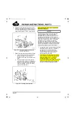
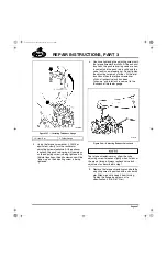
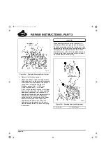
The following procedures explain how to adjust
valves on engines equipped with spring-loaded
push rods. These procedures involve using a
torque screwdriver to turn the adjusting screw.
When the preset torque value of the screwdriver
is reached, the push rod is compressed far
enough that the spring stops are in contact with
each other, thus ensuring a proper valve lash
setting.
5-111.bk Page 443 Monday, July 10, 2006 2:26 PM
Содержание ASET AC
Страница 6: ...TABLE OF CONTENTS Page iii TABLE OF CONTENTS 5 111 bk Page iii Monday July 10 2006 2 26 PM...
Страница 14: ...INTRODUCTION Page 1 INTRODUCTION 5 111 bk Page 1 Monday July 10 2006 2 26 PM...
Страница 23: ...Page 10 NOTES 5 111 bk Page 10 Monday July 10 2006 2 26 PM...
Страница 24: ...VISUAL IDENTIFICATION Page 11 VISUAL IDENTIFICATION 5 111 bk Page 11 Monday July 10 2006 2 26 PM...
Страница 28: ...DESCRIPTION AND OPERATION Page 15 DESCRIPTION AND OPERATION 5 111 bk Page 15 Monday July 10 2006 2 26 PM...
Страница 96: ...COMPONENT LOCATOR Page 83 COMPONENT LOCATOR 5 111 bk Page 83 Monday July 10 2006 2 26 PM...
Страница 99: ...Page 86 NOTES 5 111 bk Page 86 Monday July 10 2006 2 26 PM...
Страница 100: ...TROUBLESHOOTING Page 87 TROUBLESHOOTING 5 111 bk Page 87 Monday July 10 2006 2 26 PM...
Страница 140: ...MAINTENANCE Page 127 MAINTENANCE 5 111 bk Page 127 Monday July 10 2006 2 26 PM...
Страница 153: ...Page 140 NOTES 5 111 bk Page 140 Monday July 10 2006 2 26 PM...
Страница 154: ...REPAIR INSTRUCTIONS PART 1 Page 141 REPAIR INSTRUCTIONS PART 1 5 111 bk Page 141 Monday July 10 2006 2 26 PM...
Страница 383: ...Page 370 NOTES 5 111 bk Page 370 Monday July 10 2006 2 26 PM...
Страница 384: ...REPAIR INSTRUCTIONS PART 2 Page 371 REPAIR INSTRUCTIONS PART 2 5 111 bk Page 371 Monday July 10 2006 2 26 PM...
Страница 454: ...REPAIR INSTRUCTIONS PART 3 Page 441 REPAIR INSTRUCTIONS PART 3 5 111 bk Page 441 Monday July 10 2006 2 26 PM...
Страница 479: ...Page 466 NOTES 5 111 bk Page 466 Monday July 10 2006 2 26 PM...
Страница 480: ...SPECIFICATIONS Page 467 SPECIFICATIONS 5 111 bk Page 467 Monday July 10 2006 2 26 PM...
Страница 505: ...Page 492 NOTES 5 111 bk Page 492 Monday July 10 2006 2 26 PM...
Страница 506: ...SCHEMATIC ROUTING DIAGRAMS Page 493 SCHEMATIC ROUTING DIAGRAMS 5 111 bk Page 493 Monday July 10 2006 2 26 PM...
Страница 513: ...Page 500 NOTES 5 111 bk Page 500 Monday July 10 2006 2 26 PM...
Страница 514: ...SPECIAL TOOLS EQUIPMENT Page 501 SPECIAL TOOLS EQUIPMENT 5 111 bk Page 501 Monday July 10 2006 2 26 PM...
Страница 519: ...Page 506 NOTES 5 111 bk Page 506 Monday July 10 2006 2 26 PM...
Страница 520: ...APPENDIX Page 507 APPENDIX 5 111 bk Page 507 Monday July 10 2006 2 26 PM...
Страница 528: ...INDEX Page 515 INDEX Index fm Page 515 Monday July 10 2006 2 48 PM...
Страница 535: ...Page 522 NOTES Index fm Page 522 Monday July 10 2006 2 48 PM...

