Page 200
REPAIR INSTRUCTIONS, PART 1
BUSHING INSTALLATION
1. Clean the surfaces of the bushing and the
bore. Dry both surfaces with compressed
air.
2. Using a dark-colored felt-tip marker, mark
the cylinder block and bushing with a line to
facilitate correct alignment at installation.
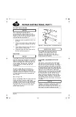
Refer to Figure 202.
202
Figure 202 — Camshaft Bushing Installation
3. Position the replacement bushing against
the side of the block at the No. 7 (rear)
bushing bore. Align the oil hole in the
bushing with the oil passage in the block.
4. Using bushing remover/installer J 42377
(with J 21428-01 Cam Bushing Installer
Set), install the bushing.
Correct installation of each camshaft bushing is
very important. If a bushing is not properly
aligned with both its oil supply and oil feed
passages in the cylinder block, either the
camshaft bushing will fail or the components
lubricated by the bushing feed will fail from
inadequate lubrication.
5. Install the camshaft bushings in sequence,
starting at the back of the cylinder block with
journal No. 7 and finishing with No. 1.
6. After all of the bushings are in place,
measure the ID of each to ensure that they
are not undersize because of burrs on the
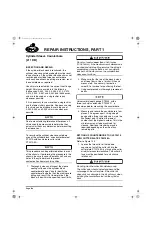
OD caused by installation (Figure 203).
Refer to the “Fits and Limits” charts in the
SPECIFICATIONS section for the correct
bushing ID dimensions.
203
Figure 203 — Camshaft Bushing ID Check
1. Bushing Oil Hole
2. Bushing
3. Pilot Adapter (J 42377)
4. Bushing
Remover/Installer
(J 21428-01 Kit)
5. Alignment Mark
6. Mounting Hole
7. Block Oil Passage
5-111.bk Page 200 Monday, July 10, 2006 2:26 PM
Содержание ASET AC
Страница 6: ...TABLE OF CONTENTS Page iii TABLE OF CONTENTS 5 111 bk Page iii Monday July 10 2006 2 26 PM...
Страница 14: ...INTRODUCTION Page 1 INTRODUCTION 5 111 bk Page 1 Monday July 10 2006 2 26 PM...
Страница 23: ...Page 10 NOTES 5 111 bk Page 10 Monday July 10 2006 2 26 PM...
Страница 24: ...VISUAL IDENTIFICATION Page 11 VISUAL IDENTIFICATION 5 111 bk Page 11 Monday July 10 2006 2 26 PM...
Страница 28: ...DESCRIPTION AND OPERATION Page 15 DESCRIPTION AND OPERATION 5 111 bk Page 15 Monday July 10 2006 2 26 PM...
Страница 96: ...COMPONENT LOCATOR Page 83 COMPONENT LOCATOR 5 111 bk Page 83 Monday July 10 2006 2 26 PM...
Страница 99: ...Page 86 NOTES 5 111 bk Page 86 Monday July 10 2006 2 26 PM...
Страница 100: ...TROUBLESHOOTING Page 87 TROUBLESHOOTING 5 111 bk Page 87 Monday July 10 2006 2 26 PM...
Страница 140: ...MAINTENANCE Page 127 MAINTENANCE 5 111 bk Page 127 Monday July 10 2006 2 26 PM...
Страница 153: ...Page 140 NOTES 5 111 bk Page 140 Monday July 10 2006 2 26 PM...
Страница 154: ...REPAIR INSTRUCTIONS PART 1 Page 141 REPAIR INSTRUCTIONS PART 1 5 111 bk Page 141 Monday July 10 2006 2 26 PM...
Страница 383: ...Page 370 NOTES 5 111 bk Page 370 Monday July 10 2006 2 26 PM...
Страница 384: ...REPAIR INSTRUCTIONS PART 2 Page 371 REPAIR INSTRUCTIONS PART 2 5 111 bk Page 371 Monday July 10 2006 2 26 PM...
Страница 454: ...REPAIR INSTRUCTIONS PART 3 Page 441 REPAIR INSTRUCTIONS PART 3 5 111 bk Page 441 Monday July 10 2006 2 26 PM...
Страница 479: ...Page 466 NOTES 5 111 bk Page 466 Monday July 10 2006 2 26 PM...
Страница 480: ...SPECIFICATIONS Page 467 SPECIFICATIONS 5 111 bk Page 467 Monday July 10 2006 2 26 PM...
Страница 505: ...Page 492 NOTES 5 111 bk Page 492 Monday July 10 2006 2 26 PM...
Страница 506: ...SCHEMATIC ROUTING DIAGRAMS Page 493 SCHEMATIC ROUTING DIAGRAMS 5 111 bk Page 493 Monday July 10 2006 2 26 PM...
Страница 513: ...Page 500 NOTES 5 111 bk Page 500 Monday July 10 2006 2 26 PM...
Страница 514: ...SPECIAL TOOLS EQUIPMENT Page 501 SPECIAL TOOLS EQUIPMENT 5 111 bk Page 501 Monday July 10 2006 2 26 PM...
Страница 519: ...Page 506 NOTES 5 111 bk Page 506 Monday July 10 2006 2 26 PM...
Страница 520: ...APPENDIX Page 507 APPENDIX 5 111 bk Page 507 Monday July 10 2006 2 26 PM...
Страница 528: ...INDEX Page 515 INDEX Index fm Page 515 Monday July 10 2006 2 48 PM...
Страница 535: ...Page 522 NOTES Index fm Page 522 Monday July 10 2006 2 48 PM...


