TROUBLESHOOTING
Page 99
CAMSHAFT TIMING AND LOBE
LIFT CHECKS
[213 CH]
Camshaft Timing Check
Correct camshaft timing is essential for proper
engine performance. Incorrect camshaft timing
may be suspected if soon after engine overhaul,
lack of performance, unusual noise or excessive
smoke is reported.
While timing marks are stamped on the flywheel,
current engines do not have a timing pointer
since setting injection pump-to-engine timing is
not necessary. However, the flywheel timing
marks can be used to check the
camshaft-to-crankshaft timing by looking up
through the hole where the timing pointer would
be located and viewing the timing marks. A pencil
point may be inserted through the timing pointer
hole to easily pinpoint the timing marks on the
scale.
Camshaft timing can be checked using either the
cylinder No. 3 or No. 4 inlet valve. For example
purposes, the No. 3 cylinder is used in the
following procedure.
1. Remove the cylinder head cover over
cylinder No. 3.
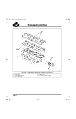
2. Locate the inlet valves for No. 3 cylinder (the
sixth valve set from the front of engine). Bar
the engine to position the No. 3 piston at top
dead center (TDC) of the compression
stroke.
3. Loosen (back off) the inlet valve rocker
adjusting screw jam nut. Ensure that the
valve yoke is correctly adjusted. Adjust the
inlet valve to zero lash.
4. Position a dial indicator (magnetic-base
type) probe on the valve spring retainer.
Preload the indicator to 1/2 indicator plunger
travel.
5. Bar the engine in the direction of normal
rotation and carefully observe the direction
in which the indicator needle travels. Use the
dial indicator to determine when the inlet
valve is fully open.
6. Stop rotating the engine when travel of the
dial indicator needle stops. If the dial
indicator needle reverses direction, the
full-open position is passed. Repeat the
procedure if this occurs.
7. Remove the timing hole cover from the
flywheel housing so that the flywheel timing
marks can be viewed. Engine timing should
be approximately 26 degrees. A difference
of approximately 10 degrees indicates that
the crankshaft-to-camshaft timing gears may
be mismatched one tooth.
Camshaft Lobe Lift Check
When diagnosing potential lifter or camshaft
failures, 0.030 inch (0.76 mm) less than the lift of
a new camshaft is considered the minimum
acceptable camshaft lobe lift for used
components. Intake lobe lift differs depending on
the camshaft part number. Camshaft lobe lift is
measured by using a dial indicator at the push
rod with the rocker arm adjusted to zero lash.
5-111.bk Page 99 Monday, July 10, 2006 2:26 PM
Содержание ASET AC
Страница 6: ...TABLE OF CONTENTS Page iii TABLE OF CONTENTS 5 111 bk Page iii Monday July 10 2006 2 26 PM...
Страница 14: ...INTRODUCTION Page 1 INTRODUCTION 5 111 bk Page 1 Monday July 10 2006 2 26 PM...
Страница 23: ...Page 10 NOTES 5 111 bk Page 10 Monday July 10 2006 2 26 PM...
Страница 24: ...VISUAL IDENTIFICATION Page 11 VISUAL IDENTIFICATION 5 111 bk Page 11 Monday July 10 2006 2 26 PM...
Страница 28: ...DESCRIPTION AND OPERATION Page 15 DESCRIPTION AND OPERATION 5 111 bk Page 15 Monday July 10 2006 2 26 PM...
Страница 96: ...COMPONENT LOCATOR Page 83 COMPONENT LOCATOR 5 111 bk Page 83 Monday July 10 2006 2 26 PM...
Страница 99: ...Page 86 NOTES 5 111 bk Page 86 Monday July 10 2006 2 26 PM...
Страница 100: ...TROUBLESHOOTING Page 87 TROUBLESHOOTING 5 111 bk Page 87 Monday July 10 2006 2 26 PM...
Страница 140: ...MAINTENANCE Page 127 MAINTENANCE 5 111 bk Page 127 Monday July 10 2006 2 26 PM...
Страница 153: ...Page 140 NOTES 5 111 bk Page 140 Monday July 10 2006 2 26 PM...
Страница 154: ...REPAIR INSTRUCTIONS PART 1 Page 141 REPAIR INSTRUCTIONS PART 1 5 111 bk Page 141 Monday July 10 2006 2 26 PM...
Страница 383: ...Page 370 NOTES 5 111 bk Page 370 Monday July 10 2006 2 26 PM...
Страница 384: ...REPAIR INSTRUCTIONS PART 2 Page 371 REPAIR INSTRUCTIONS PART 2 5 111 bk Page 371 Monday July 10 2006 2 26 PM...
Страница 454: ...REPAIR INSTRUCTIONS PART 3 Page 441 REPAIR INSTRUCTIONS PART 3 5 111 bk Page 441 Monday July 10 2006 2 26 PM...
Страница 479: ...Page 466 NOTES 5 111 bk Page 466 Monday July 10 2006 2 26 PM...
Страница 480: ...SPECIFICATIONS Page 467 SPECIFICATIONS 5 111 bk Page 467 Monday July 10 2006 2 26 PM...
Страница 505: ...Page 492 NOTES 5 111 bk Page 492 Monday July 10 2006 2 26 PM...
Страница 506: ...SCHEMATIC ROUTING DIAGRAMS Page 493 SCHEMATIC ROUTING DIAGRAMS 5 111 bk Page 493 Monday July 10 2006 2 26 PM...
Страница 513: ...Page 500 NOTES 5 111 bk Page 500 Monday July 10 2006 2 26 PM...
Страница 514: ...SPECIAL TOOLS EQUIPMENT Page 501 SPECIAL TOOLS EQUIPMENT 5 111 bk Page 501 Monday July 10 2006 2 26 PM...
Страница 519: ...Page 506 NOTES 5 111 bk Page 506 Monday July 10 2006 2 26 PM...
Страница 520: ...APPENDIX Page 507 APPENDIX 5 111 bk Page 507 Monday July 10 2006 2 26 PM...
Страница 528: ...INDEX Page 515 INDEX Index fm Page 515 Monday July 10 2006 2 48 PM...
Страница 535: ...Page 522 NOTES Index fm Page 522 Monday July 10 2006 2 48 PM...


