Page 382
REPAIR INSTRUCTIONS, PART 2
EXHAUST VALVE YOKE PIN
AND VALVE ROTATOR
INSPECTION AND
REPLACEMENT CRITERIA
(IN-CHASSIS)
On engines that have experienced a camshaft
failure, it is likely that excessive valve lash exists
at the locations where the cam lobe/lifter roller is
severely damaged or worn. Excessive valve lash
can cause damage to the exhaust valve yoke
guide pins and the valve rotators. To prevent a
repeat engine failure, integrity of the guide pins
and valve rotators must be determined, and
damaged rotators replaced. Procedures for
determining valve rotator integrity are as follows:
1. Inspect the oil pan magnetic drain plug for
very small pieces of broken-up coil springs.
These small pieces of spring coils are
approximately 0.0150
″
in diameter, and are
what remains of a rotator internal spring that
has broken apart.
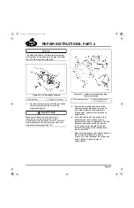
2. Remove the rocker shafts and use a magnet
to search all accessible top surfaces of the
cylinder head for pieces of rotator springs.
Do not wash the top surfaces of the head. If any
pieces of rotator spring are washed down the
push rod hole, cam/lifter failure will result.
When the rotator internal spring breaks apart, it
will break into small pieces of coil. These small
pieces will remain inside the rotator for a period of
time, but will eventually migrate out of the rotator.
The greatest concentration of these small spring
coil pieces will be found in the valve spring seat
counterbore areas of the cylinder head. To find
these small pieces, it will be necessary to remove
the rotator and valve spring to check the spring
seat counterbore area.
3. Perform the following inspections to
determine the likely locations for damaged
valve rotators:
a.
Inspect and record the locations where
the cam lobes (both inlet and exhaust)
and the lifter rollers exhibit
moderate-to-severe wear/damage.
Rotate the engine to bring the piston to
top-dead-center at that location, then
remove the valve keys and carefully
remove the rotator and valve spring.
Use a magnet to search for and remove
pieces of the rotator spring coil.
b.
If the engine is equipped with a
J-Tech™ engine brake, measure the
exhaust yoke actuating pin adjusting
screw assemblies and record the
locations where any screw has an
overall height dimension of
0.945
″
(24.00 mm) or less.
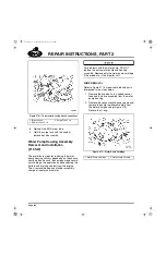
c.
If the actuating pin adjusting screw
assemblies measure 0.945
″
(24.00 mm) or less, the valve yoke
guide pin at the location of this extreme
wear must be replace. Use dowel
extrator (tool No. PT 6575) to remove
the guide pins.
5-111.bk Page 382 Monday, July 10, 2006 2:26 PM
Содержание ASET AC
Страница 6: ...TABLE OF CONTENTS Page iii TABLE OF CONTENTS 5 111 bk Page iii Monday July 10 2006 2 26 PM...
Страница 14: ...INTRODUCTION Page 1 INTRODUCTION 5 111 bk Page 1 Monday July 10 2006 2 26 PM...
Страница 23: ...Page 10 NOTES 5 111 bk Page 10 Monday July 10 2006 2 26 PM...
Страница 24: ...VISUAL IDENTIFICATION Page 11 VISUAL IDENTIFICATION 5 111 bk Page 11 Monday July 10 2006 2 26 PM...
Страница 28: ...DESCRIPTION AND OPERATION Page 15 DESCRIPTION AND OPERATION 5 111 bk Page 15 Monday July 10 2006 2 26 PM...
Страница 96: ...COMPONENT LOCATOR Page 83 COMPONENT LOCATOR 5 111 bk Page 83 Monday July 10 2006 2 26 PM...
Страница 99: ...Page 86 NOTES 5 111 bk Page 86 Monday July 10 2006 2 26 PM...
Страница 100: ...TROUBLESHOOTING Page 87 TROUBLESHOOTING 5 111 bk Page 87 Monday July 10 2006 2 26 PM...
Страница 140: ...MAINTENANCE Page 127 MAINTENANCE 5 111 bk Page 127 Monday July 10 2006 2 26 PM...
Страница 153: ...Page 140 NOTES 5 111 bk Page 140 Monday July 10 2006 2 26 PM...
Страница 154: ...REPAIR INSTRUCTIONS PART 1 Page 141 REPAIR INSTRUCTIONS PART 1 5 111 bk Page 141 Monday July 10 2006 2 26 PM...
Страница 383: ...Page 370 NOTES 5 111 bk Page 370 Monday July 10 2006 2 26 PM...
Страница 384: ...REPAIR INSTRUCTIONS PART 2 Page 371 REPAIR INSTRUCTIONS PART 2 5 111 bk Page 371 Monday July 10 2006 2 26 PM...
Страница 454: ...REPAIR INSTRUCTIONS PART 3 Page 441 REPAIR INSTRUCTIONS PART 3 5 111 bk Page 441 Monday July 10 2006 2 26 PM...
Страница 479: ...Page 466 NOTES 5 111 bk Page 466 Monday July 10 2006 2 26 PM...
Страница 480: ...SPECIFICATIONS Page 467 SPECIFICATIONS 5 111 bk Page 467 Monday July 10 2006 2 26 PM...
Страница 505: ...Page 492 NOTES 5 111 bk Page 492 Monday July 10 2006 2 26 PM...
Страница 506: ...SCHEMATIC ROUTING DIAGRAMS Page 493 SCHEMATIC ROUTING DIAGRAMS 5 111 bk Page 493 Monday July 10 2006 2 26 PM...
Страница 513: ...Page 500 NOTES 5 111 bk Page 500 Monday July 10 2006 2 26 PM...
Страница 514: ...SPECIAL TOOLS EQUIPMENT Page 501 SPECIAL TOOLS EQUIPMENT 5 111 bk Page 501 Monday July 10 2006 2 26 PM...
Страница 519: ...Page 506 NOTES 5 111 bk Page 506 Monday July 10 2006 2 26 PM...
Страница 520: ...APPENDIX Page 507 APPENDIX 5 111 bk Page 507 Monday July 10 2006 2 26 PM...
Страница 528: ...INDEX Page 515 INDEX Index fm Page 515 Monday July 10 2006 2 48 PM...
Страница 535: ...Page 522 NOTES Index fm Page 522 Monday July 10 2006 2 48 PM...

