REPAIR INSTRUCTIONS, PART 1
Page 213
CRANKSHAFT AND
FLYWHEEL BENCH
PROCEDURES
General Information
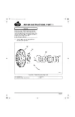
Current-production flywheels no longer have the
timing grooves milled into the face surface.
Crankshaft Inspection
[212 HP]
GENERAL INSTRUCTIONS
All bearing surfaces must be free of grit and
burrs. Small particles of dust and dirt left between
the crankshaft and bearings will cause rapid wear
and scoring of the crankshaft journal and inserts.
Any foreign material left between the crankshaft
bearing inserts and caps will cause distortion of
the insert and a reduction in operating clearance
at that point. The resulting frictional heat at the
point of distortion will cause the bearing material
to melt away from the steel backing. Such melted
material will create further hot spots until
complete bearing failure occurs. Anything that
interferes with the operating clearance of a
bearing and the proper dissipation of heat will
affect bearing life. Cleanliness cannot be
overstressed.
INSPECTION
1. Inspect the crankshaft journals for out of
round, taper and poor surface finish.
2. Visually check the crankshaft for any
apparent cracks, worn journals and damage
to threads, dowel pin or main drive gear.
3. Magnaflux the crankshaft to check further for
cracks. This process requires special
equipment and application methods.
4. Using standard machinists’ inspection
practice, check the crankshaft to ensure that
it is straight.
5. Measure the crankshaft journals with a
micrometer. Measure each journal in two
locations, 90 degrees apart, and record the
measurements.
6. Check the measurements against the
specifications listed under Fits and Limits in
the SPECIFICATIONS section.
7. If the crankshaft journals are worn, out of
round, or tapered, replace the crankshaft.
New or exchange crankshafts are available
from MACK Parts Distribution Centers.
Crankshaft regrinding by anyone other than Mack
Trucks, Inc. is NOT recommended due to the
tight control required for maintaining geometrical
tolerances, and the hardened characteristics of
crankshaft journals and journal fillets.
If the crankshaft main journals or connecting rod
journals are not a standard size, be sure to use
properly sized bearing inserts when reassembling
the engine. Bearing insert sizing is identified with
a “P” following the part number, and is stamped
on the back side of the bearing insert. For
example, if a journal is 0.010 inch (0.254 mm)
undersize, a 0.010-inch undersize bearing is
required and will be stamped “P10.”
Some crankshafts may have journals which are
0.002 inch (0.0508 mm) undersize. These
crankshafts are marked by a streak of white paint
adjacent to the journal. Always check the journals
to ensure that the bearing inserts used are of the
proper size.
Crankshaft Dowel Pin Replacement
[212 HA]
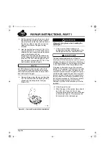
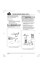
Current-production crankshafts are equipped with
a blade-type flywheel-to-crankshaft dowel pin
installed in the rear flange directly opposite the
manufacturing locator hole. Hole sizes are as
follows:
앫
Manufacturing locator hole — approximately
1/2 inch (12.7 mm) in diameter and 3/8 inch
(9.52 mm) deep; used in the manufacturing
process
앫
Flywheel dowel pin hole — approximately
9/16 inch (14.29 mm) in diameter by 7/8 inch
(22.23 mm) deep
5-111.bk Page 213 Monday, July 10, 2006 2:26 PM
Содержание ASET AC
Страница 6: ...TABLE OF CONTENTS Page iii TABLE OF CONTENTS 5 111 bk Page iii Monday July 10 2006 2 26 PM...
Страница 14: ...INTRODUCTION Page 1 INTRODUCTION 5 111 bk Page 1 Monday July 10 2006 2 26 PM...
Страница 23: ...Page 10 NOTES 5 111 bk Page 10 Monday July 10 2006 2 26 PM...
Страница 24: ...VISUAL IDENTIFICATION Page 11 VISUAL IDENTIFICATION 5 111 bk Page 11 Monday July 10 2006 2 26 PM...
Страница 28: ...DESCRIPTION AND OPERATION Page 15 DESCRIPTION AND OPERATION 5 111 bk Page 15 Monday July 10 2006 2 26 PM...
Страница 96: ...COMPONENT LOCATOR Page 83 COMPONENT LOCATOR 5 111 bk Page 83 Monday July 10 2006 2 26 PM...
Страница 99: ...Page 86 NOTES 5 111 bk Page 86 Monday July 10 2006 2 26 PM...
Страница 100: ...TROUBLESHOOTING Page 87 TROUBLESHOOTING 5 111 bk Page 87 Monday July 10 2006 2 26 PM...
Страница 140: ...MAINTENANCE Page 127 MAINTENANCE 5 111 bk Page 127 Monday July 10 2006 2 26 PM...
Страница 153: ...Page 140 NOTES 5 111 bk Page 140 Monday July 10 2006 2 26 PM...
Страница 154: ...REPAIR INSTRUCTIONS PART 1 Page 141 REPAIR INSTRUCTIONS PART 1 5 111 bk Page 141 Monday July 10 2006 2 26 PM...
Страница 383: ...Page 370 NOTES 5 111 bk Page 370 Monday July 10 2006 2 26 PM...
Страница 384: ...REPAIR INSTRUCTIONS PART 2 Page 371 REPAIR INSTRUCTIONS PART 2 5 111 bk Page 371 Monday July 10 2006 2 26 PM...
Страница 454: ...REPAIR INSTRUCTIONS PART 3 Page 441 REPAIR INSTRUCTIONS PART 3 5 111 bk Page 441 Monday July 10 2006 2 26 PM...
Страница 479: ...Page 466 NOTES 5 111 bk Page 466 Monday July 10 2006 2 26 PM...
Страница 480: ...SPECIFICATIONS Page 467 SPECIFICATIONS 5 111 bk Page 467 Monday July 10 2006 2 26 PM...
Страница 505: ...Page 492 NOTES 5 111 bk Page 492 Monday July 10 2006 2 26 PM...
Страница 506: ...SCHEMATIC ROUTING DIAGRAMS Page 493 SCHEMATIC ROUTING DIAGRAMS 5 111 bk Page 493 Monday July 10 2006 2 26 PM...
Страница 513: ...Page 500 NOTES 5 111 bk Page 500 Monday July 10 2006 2 26 PM...
Страница 514: ...SPECIAL TOOLS EQUIPMENT Page 501 SPECIAL TOOLS EQUIPMENT 5 111 bk Page 501 Monday July 10 2006 2 26 PM...
Страница 519: ...Page 506 NOTES 5 111 bk Page 506 Monday July 10 2006 2 26 PM...
Страница 520: ...APPENDIX Page 507 APPENDIX 5 111 bk Page 507 Monday July 10 2006 2 26 PM...
Страница 528: ...INDEX Page 515 INDEX Index fm Page 515 Monday July 10 2006 2 48 PM...
Страница 535: ...Page 522 NOTES Index fm Page 522 Monday July 10 2006 2 48 PM...


